By Robert G. Segel
History
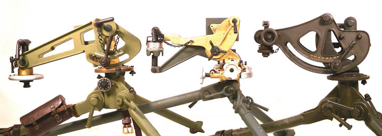
There were three versions of tripods manufactured specifically for the Browning Model of 1917 and M1917A1 water-cooled heavy machine guns and accepted as Standard. In order, they were the Model of 1917 tripod, the Model of 1918 tripod (also known at the time as the Cygnet Tripod) and the M1917A1 tripod. The Model of 1917 tripod was covered in detail in Vol. 10, No. 4, January 2007 issue of Small Arms Review.
The Model of 1917 tripod, while an excellent and stable platform, did not lend itself well to indirect fire, was heavy and relatively complicated to use. Another problem was that a total of 72,500 Model of 1917 machine guns were built during and immediately after World War I but there were only approximately 20,000 Model of 1917 tripods manufactured (which is why the Vickers Mk IV tripod was often pressed into service for use with the Model of 1917 machine gun). In an attempt to address all of the issues mentioned above, in 1918, a new tripod was quickly developed and adopted as the Model of 1918.
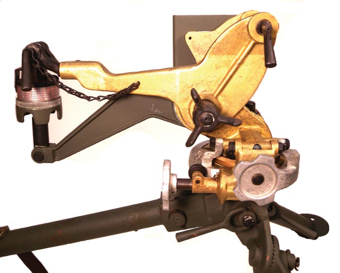
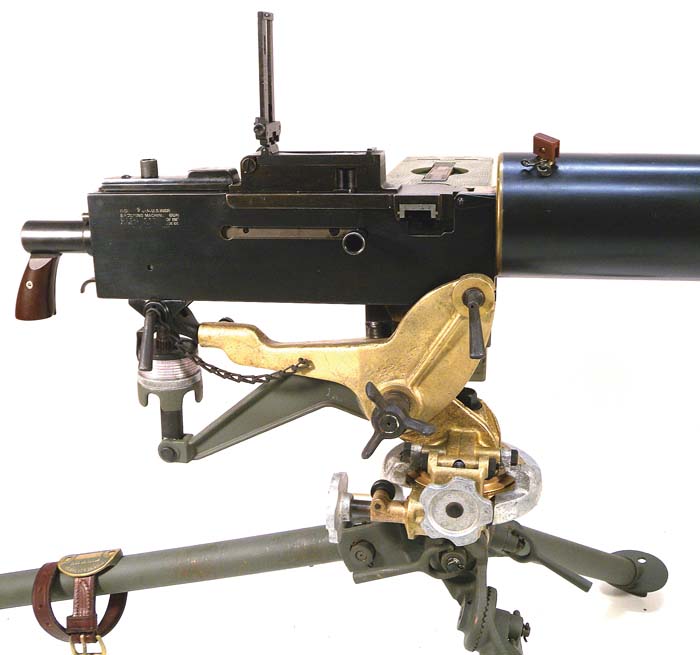
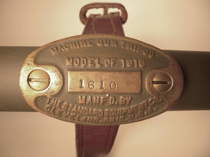
There were four manufacturers of the Model of 1918 tripod. They were: The New Britain Machine Company of New Britain, Connecticut, The Nelson Blower and Furnace Company of Boston, Massachusetts, The Winton Company of Cleveland, Ohio and The Standard Equipment Company of Cleveland, Ohio. In all, 31,700 Model of 1918 tripods were produced.
Unfortunately, the new Model of 1918 tripod proved to be a debacle. With its five leg adjustment clamps for three legs, the gun was exceptionally difficult to set up quickly, the cradle arm was fragile and was not a rigid platform for the gun due to lack of support at the rear of the cradle causing unacceptable disbursement of fire, and the Model of 1917 Belt Box did not fit correctly in the flange bracket attached to the side of the cradle. These attributes made the tripod extremely undesirable and generally despised by the troops that had to use them. So reviled by the soldiers and their commanding officers as slow to set up, unstable and unsafe, they clamored to be reissued the older Model of 1917 tripods. Their requests, surprisingly, did not fall on deaf ears and the Model of 1918 tripod was withdrawn from service, placed in storage, designated as Limited Standard and the Model of 1917 tripod returned to service with some slight modifications until the M1917A1 tripod was developed in the 1930s.
The inventory of Model of 1918 tripods in storage were eventually disposed of with approximately 6,000 of them being sent to England in 1940 under the Lend-Lease program along with a similar number of Model of 1917 machine guns. It is not known exactly what happened to the remaining inventory of Model of 1918 tripods but it is strongly suspected they were eventually scrapped and destroyed sometime immediately after World War II.
The Model of 1918 tripod is a very rare accessory to find in the United States, but because of the numbers sent to England in 1940, and used, they are commonly found in museums across Great Britain.
Description
The description of the Model of 1918 Tripod is best related in Machine Gun Service Regulations, Section 22, prepared by the Ordnance Department in collaboration with the Machine Gun Training Center, Camp Hancock, Augusta, Georgia. War Plans Division, Washington, D.C., January, 1919, War Department Document No. 856.
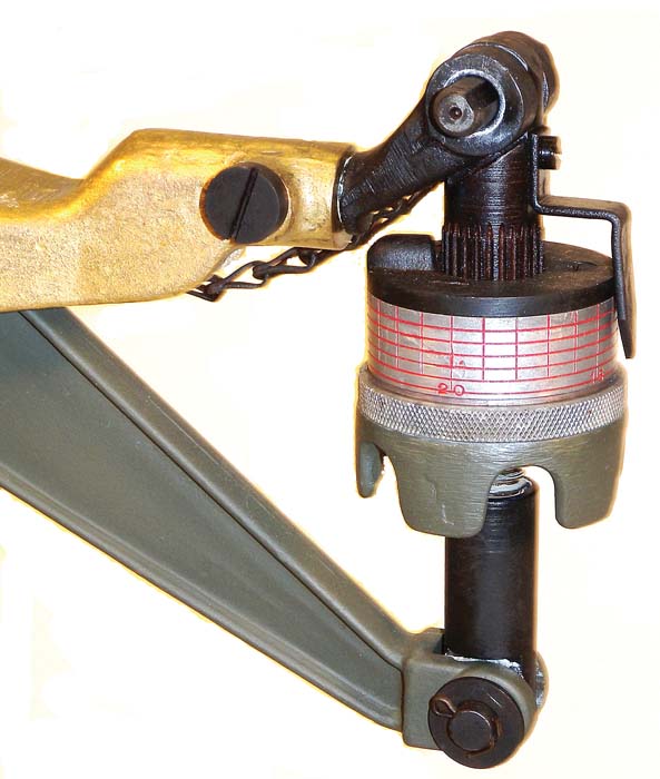
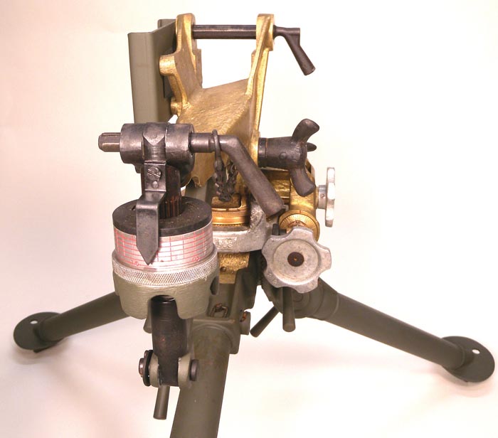
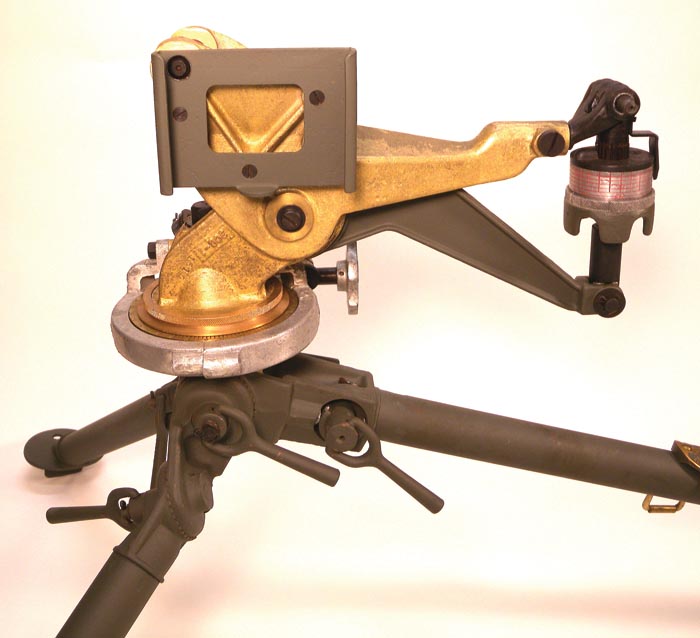
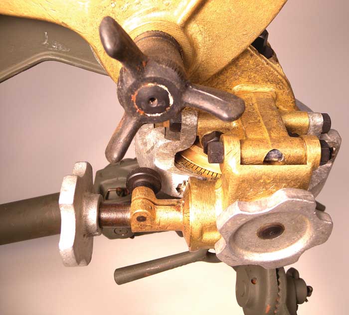
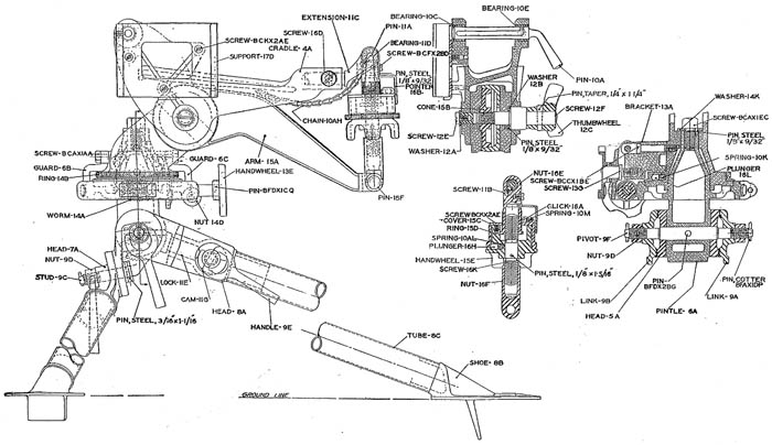
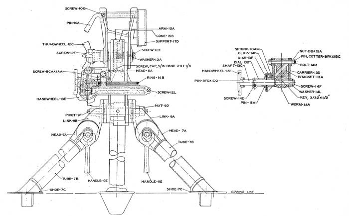
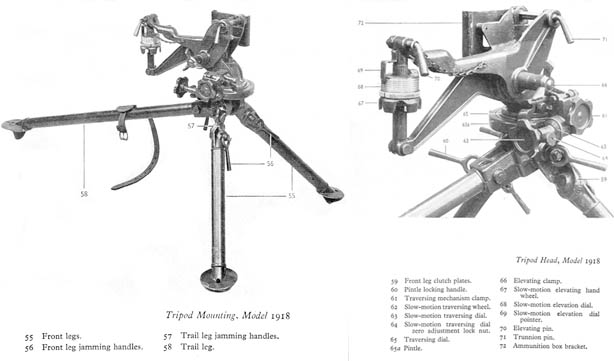
The Machine Gun Tripod, Model of 1918, usually known as the Cygnet Tripod, consists broadly of eight major parts: 1, the cradle; 2, the cradle support arm; 3, elevating mechanism; 4, traversing head; 5, pintle; 6, gear guard; 7, traversing worm; and 8, tripod legs.
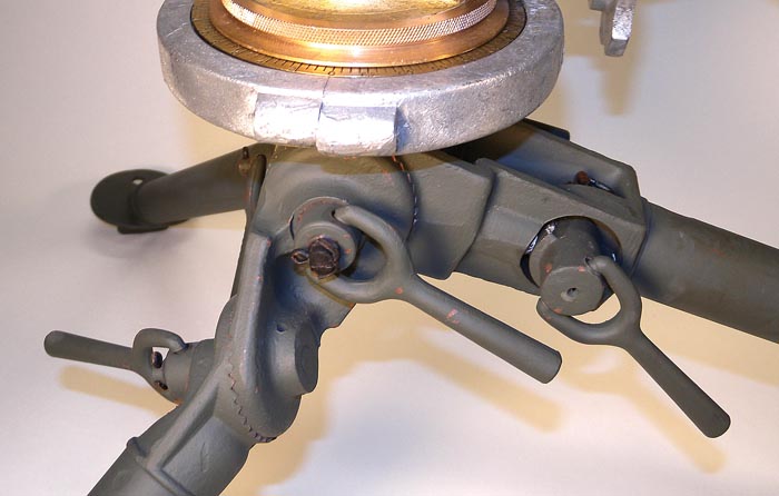
The cradle is a bronze casting and is the intermediate member between the gun and the tripod mechanism. It floats about its horizontal axis. A bracket for holding an ammunition box is also attached.The cradle support arm supports the rear end of the cradle through the elevating mechanism. This arm is pivoted horizontally about the same point as the cradle and moves with it when the gun is elevated or depressed about the central axis.The elevating mechanism is connected between the rear end of the cradle and the rear end of the cradle support arm and provides a means for measuring small amounts of elevation or depression. It has the capacity of 138 mils.The traversing head supplies the bearings upon which the head revolves. Through upward extending lugs it also supplies the bearing upon which the cradle and cradle support arm revolve. This revolution is governed by adjusting the wing headed clamping nut on the screw which passes through this upper bearing.The pintle is of bronze and has a leg lug on its under side, a movable circular scale and hollow cone pintle on its upper side and a worm gear about its circumference. It is on this part that the traversing head revolves, being bolted through its center to the axis of the cone pintle.The gear guard is made of aluminum and encircles and embraces the worm gear of the pintle. It is formed in half circle sections, bolt jointed at one side and bolted to the worm bracket of the traversing head at the other side. The gear guar moves with the traversing head. The traversing worm is mounted in an open sector of the gear guard in a carrier pendantly hinged to the worm bracket of the traversing head. It is moved in and out of engagement through the action of a flat headed clamping screw.The tripod legs are of steel tubing having flat disked fin-based feet with holes in each disk for pegging down, if required, and are pivoted to the leg lug on the under side of the pintle by a traverse pin with threaded cotter pin retained clamping nuts on each end. The long rearward tripod leg has a forked upper end which embraces the leg lug on the pintle. The two outside surfaces of the leg head are cut in the form of serrated disks. The two short forward legs of the tripod are made in two sections and jointed with serrated disks. The upper ends of the legs are also serrated and engage with the serrations on the upper end of the rear leg.
A leather strap attached to the rear leg provides means for strapping the legs together when folded for packing or transportation. In this case the legs are placed at right angles to the tripod head and parallel with the gun cradle and its support and all clamps tightened.
Elevating Mechanism
A slow-motion elevating hand wheel is provided with a mil clicking device. Turned in a forward direction (i.e. forwards away from the gunner) raises the gun, and turned in the reverse direction lowers the gun. Each click represents 1 mil alteration.
Larger alterations in angles of elevation than that provided by the slow-motion elevating hand wheel may be accomplished by loosening the elevating clamp and raising or lowering the gun.
Traversing Mechanism
A slow-motion mil clicking traversing gear is provided. With the traversing gear clamp screwed up so that the teeth of the traversing gear are engaged, the traversing handle when rotated in a clockwise direction traverses the gun to the left, and when rotated in an anti-clockwise direction traverses the gun to the right. Each click represents 1 mil traverse.
When the traversing gear clamp is unscrewed so that the traversing gear teeth are disengaged, the gun is free to be traversed by hand.
Small angles of traverse can be read off from the small dial on the traversing hand wheel. Zero setting can be established by loosening the dial lock nut and tightened at the desired setting.
Larger alterations in angles of traverse than that provided by the slow-motion traversing wheel may be accomplished by loosening the traversing clamp and traversing the gun by hand. Angles of traverse may be read off from the traversing dial which is provided with an adjustable zero setting that can be turned by hand.
Ammunition Boxes
The early wood ammunition boxes for the Browning were well made of high quality oak with dove-tailed joints and were designed to hold one loaded 250-round fabric belt. Designated as the Model of 1917 Belt Box, they were intended for use on the Model of 1917 tripod. These boxes had slits cut into the sides at the front that allowed the box to be mounted into a flanged bracket mounted on the left side of the tripod head. These rectangular boxes all had square corners.
When the Model of 1918 tripod was developed, it was found that the Model of 1917 Belt Box did not fit the new Model of 1918 tripod as the bottom corner of the box nearest to the gun would not clear the outline of the cradle and would not fit properly in the ammunition box bracket holder attached to the left side of the tripod cradle. Thus, a 45-degree angled cut was made on the bottom/side of the box. This ammunition box was designated as the Model of 1918 Belt Box and all subsequent wood Browning boxes were manufactured with this 45-degree cut along the bottom and fit all models of tripods. Other than the 45-degree angled cut, the Model of 1918 Belt Box was identical with the Model of 1917 Belt Box. Specifications Model of 1918 Tripod
Weight: 45 pounds
Extreme height when set up: 2 ft. 6 in.
Minimum height when set up: 1 ft. 0 in.
Total capacity of elevation: 600 mils
Total capacity of depression: 745 mils
Capabilities of slow elev. mechanism: 138 mils
Capabilities: Quick traversing, Slow traversing, Quick searching, Slow searching

| This article first appeared in Small Arms Review V13N11 (August 2010) |


