By Charles Brown
Shortly after World War I ended, the U.S. Army found itself in possession of about 70,000 Model of 1917 .30 caliber water-cooled Browning machine guns, the majority of which were new in the crate. They also had to resolve the problem of bulged side plates, broken breech lock cams and bottom plates that cropped up during combat use in France.
Many fingers have been pointed in various directions attempting to fix blame for the failure to perform as advertised: bad steel, poor workmanship, inadequate inspection, etc., but the root cause of the problem was the method by which the bottom plate was attached to the side plates. The bottom plate slipped into grooves milled into the side plates and was peened or crimped in place. It was a design flaw, pure and simple, which likely would have been discovered had more extensive testing been done before fielding the weapon.
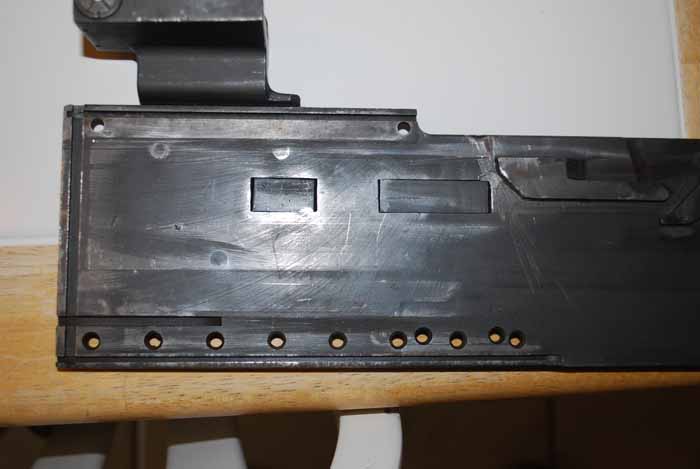
Post-war, the Ordnance Department promptly went to work on the problem and after extensive testing determined that the quick and dirty (not to mention cheap) fix was the installation of a “U” shaped reinforcing stirrup riveted to the side plates in the breech cam lock region of the casing. This retrofit could be accomplished without disassembly of the casing and at relatively low cost. The cost factor was extremely important as military budgets and manpower were slashed, and the political landscape shifted from rampant jingoism back to a decidedly isolationist bent and the traditional public fears of militarism and a large standing army returned. In 1920, the production of the stirrups began along with the installation on Model of 1917, Tank, and Aircraft Brownings being refurbished before being placed in stores and weapons being returned to depots for repairs.
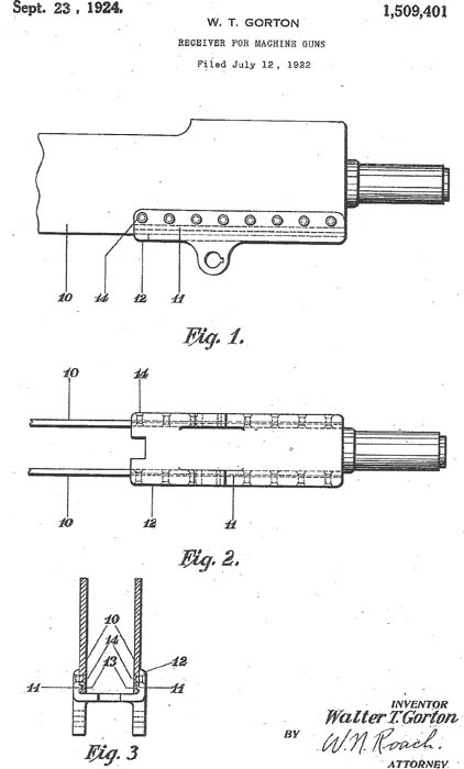
Not everybody connected with the Ordnance Department thought the stirrup fix was the best approach. One such person was Captain Walter T. Gorton, an Ordnance Officer assigned to the Springfield Armory. Captain Gorton took the “big picture” view and designed a bottom plate that not only provided the required reinforcement in spades but also added an integral elevating bracket eliminating the separate bracket and the four attaching screws. In 1922 Captain Gorton applied for and later received U.S. Patent 1,509,401 on Sept. 23, 1924. Because of the Act of March 3, 1883, employees of the U.S. Government who developed patents in connection with their official duties could receive no royalties, and any person in the United States was free to use the design. Like John C. Garand, developer of “the greatest battle implement ever devised,” Captain Gorton never received a dime in royalties. Unfortunately, the Captain’s design would require manufacturing a rather complicated part and the removal of the existing bottom plate; something deemed overkill when the stirrup modification would do just fine for an army caught in budget cuts and growing increasingly stale at the practice of arms following the “War to end all wars.”
Gorton’s design continued to gather dust until 1936 when two seemingly unrelated events combined to bring the improved bottom plate design to the forefront. The first event was a change in the design of the elevating mechanism of the M1917A1 tripod which required that the elevating bracket be precisely located and perpendicular to the axis of the bore, something that the original Model of 1917 “dove-tail” bottom plate with its separately attached elevation bracket lacked. The second event was Congress taking the view that loosening the purse strings to allow upgrading and conversion of new-in-the-box Model of 1917s to M1917A1 and M1919A4 air cooled weapons was preferable and much less expensive than a new weapons development program which the Army had been hounding them for. An additional benefit was that any Model of 1918 Aircraft guns not required by the Army Air Corps or obsolete Tank Guns could also be converted to M1919A4’s.
Gorton’s design added the needed strength to the casing assembly and provided for a uniform location for the elevating mechanism attachment for both the M1917A1 and new M2 tripods. The Ordnance Department had completed the conversion of the Model of 1917 drawings from the old Class and Division system to the letter prefix system in 1931 and had assigned the drawing number C8464 to the dove-tail bottom plate.
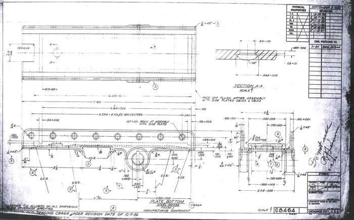
For reasons not at all clear, and in violation of Ordnance Department regulation, when the drawing for Gorton’s plate was produced in September 1936, it was assigned the same drawing number as the dove-tail plate even though these parts were not in any way interchangeable. When the D35392 aka C8464 flanged bottom plate was being developed for the M1919A2 and the A4, the Cavalry requested that the rectangular boss on the bottom just ahead of the T&E attachment point be included. This modification was desired for use with the horse pack Machine Gun Hanger M3 for a more secure attachment of the gun to the hanger. It continued to be included in the design until the end of production even though pack transport of machine guns was mostly a distant memory. The original design for the new bottom plate was dimensioned to be used on new production weapons. It appears that as the rebuild process developed it was discovered that when the weapons were originally assembled the process of compressing or crimping the bottom edge of the side plates into the tongues of the dove-tail bottom plate produced very uneven results. The interior casing dimensions were consistent, but height of the side plates after assembly varied. Since the new bottom plate had side plate grooves milled to accommodate new side plates the random height side plates on the weapons being rebuilt caused changes to the interior dimensions of the casing assembly. Nearly every one of these weapons undergoing rebuild was slightly different.
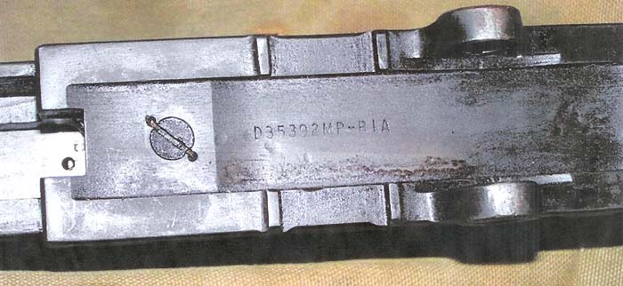
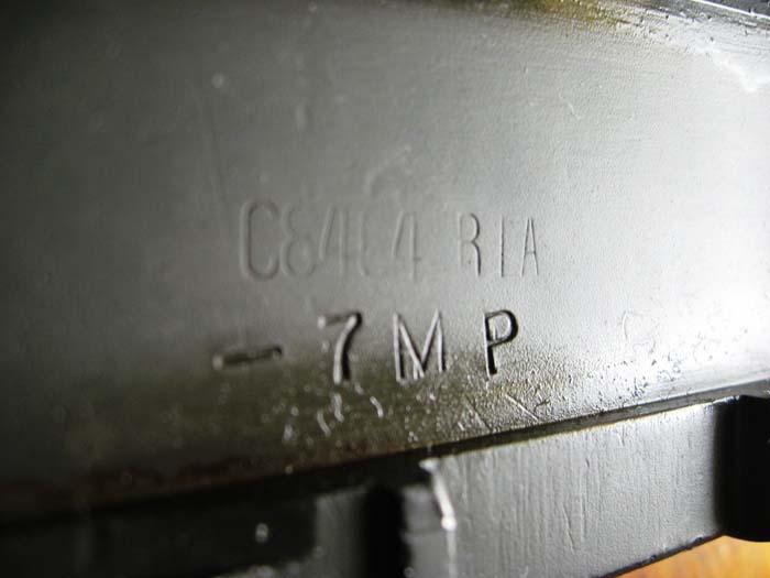
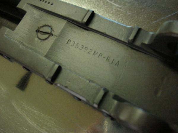
The solution to this new problem was to mill the bottom of all the side plates of weapons undergoing rebuild to a standard height dimension and produce a bottom plate with side plate grooves specifically dimensioned for the milled side plates. It appears that these special purpose bottom plates were removed from the production line at some point before the side plate grooves were cut and finished with the necessary changes. From samples measured, it appears that the modified bottom plates had side plate grooves about .037 shallower than the standard bottom plate. In order to differentiate between standard plates and plates intended to be used in the rebuild process the rebuild plates were marked “MP” in addition to the standard piece mark. It is believed by the author that “MP” indicated “Modified Part.” However, it could also mean “Modified Plate” or none of the above, as there isn’t any documentation discovered so far explaining what “MP” actually meant.
By February 1938 it was decided that since the Gorton bottom plate was to be used on the M1917A1 and the M1919A4, the drawing would be renumbered to D35392 to end the confusion of having two different parts, the original dove-tail and the flanged Gorton bottom plate with the same drawing number. The practice of marking plates intended for use in the conversion process continued with the plates now being marked D35392 MP and the makers marking. Some MP bottom plates had piece mark suffixes which only indicate that the part is made to some revision specification; it has nothing to do with the fact that it is a special purpose bottom plate. No drawings of either of these two modified bottom plates have been discovered as of yet.
Now there were two differently marked special purpose bottom plates and things were about to take a turn for the worse. By July 1940, with a war on in Europe and the weapons rebuilding/conversion rebuilding process well under way, Rock Island Arsenal decided to create a new drawing of the special purpose bottom plate with yet another piece mark. This new drawing was numbered D37887 and contained only those dimensions needed to cut the special depth side plate grooves. It also contains notes indicating that all other dimensions required are to be obtained from drawing D35392 and the part is for modifications only.
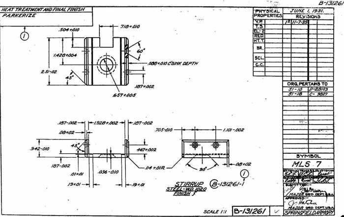
Comparing the two drawings shows a difference in the side plate groove depth of .040 which could vary slightly for manufacturing tolerances. Now there were three differently piece marked special purpose bottom plates. Sometimes the more you try to fix something the worse you make it.
From what we understand about what actually went on, RIA did all the conversions of Model of 1917 to M1919A4 along with all the conversions of Model of 1918 Aircraft guns, Model of 1919 Tank guns and M1919A2’s to M1919A4’s. From what has been observed so far in the way of bottom plates, RIA made all the conversion bottom plates used by various ordnance facilities in the rebuild of Model of 1917 to M1917A1 guns. The 1943 and 1944 SNL (Standard Nomenclature List) List of All Parts for the M1919A4, A5, and A6 carries a notation for the ordering of bottom plates, “Note 1. Plate, bottom D37887 should be ordered for guns that have been modified. These guns may be identified by the marking C8464-MP, D35392-MP or D37887 which appear on the underside of the bottom plate.”
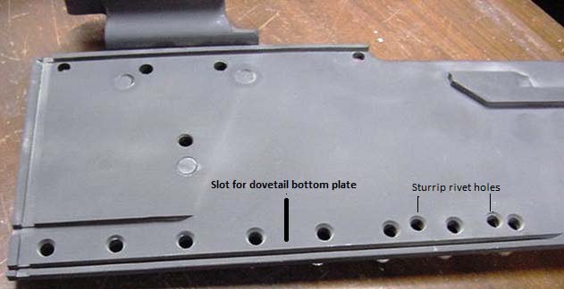
How one was supposed to order the D37887 bottom plate is left up in the air because there is no SNL listing of this plate and consequently no stock number with which to order it. While all this happened nearly 75 years ago, parts kits imported from Israel and elsewhere that were involved in the conversion process turn up with surprising regularity. Their new owners sometimes wonder about oddly numbered bottom plates and left side plates with the groove for the dove-tail bottom plate and a couple of extra holes where the reinforcing stirrup was riveted on or filled in cuts for aircraft synchronizers. Some of these weapons have been involved in more conversions than a tent revival meeting. These strange visitors from the past just make life and the Browning story more interesting.
| This article first appeared in Small Arms Review V16N3 (September 2012) |


