By Robert Segel
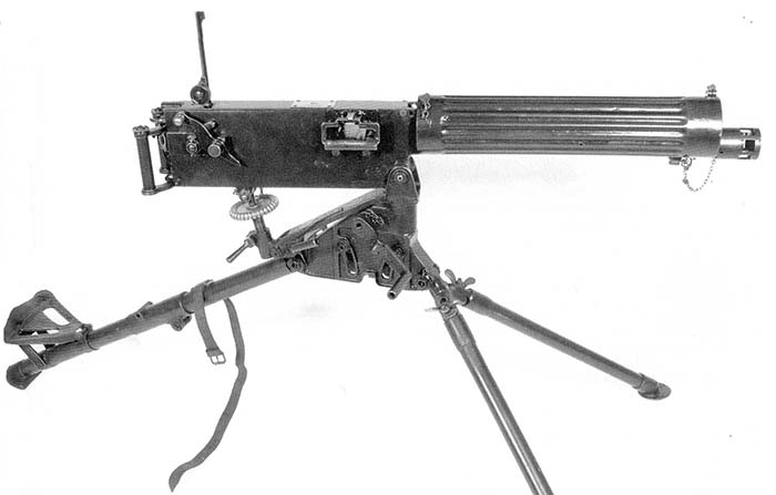
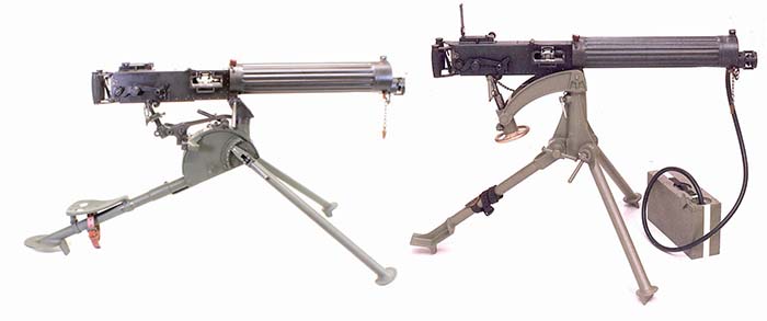
The U.S. Automatic Machine Gun Tripod Model of 1915 is one of the mysteries of early U.S. machine gun development and accessories. Rarely seen anywhere in museums or in any private collection, it was intended to be the standard issue tripod for the U.S. Colt Model of 1915 Vickers: but it never came to be other than some initial prototypes and an occasional fleeting glimpse of a single picture or drawing. The Model of 1915 tripod was made by Springfield Armory but never made it into full production there or at Colt. It is, in fact, an almost identical copy of the British Vickers Mark “J” commercial tripod… and the story of this tripod begins there with the British.
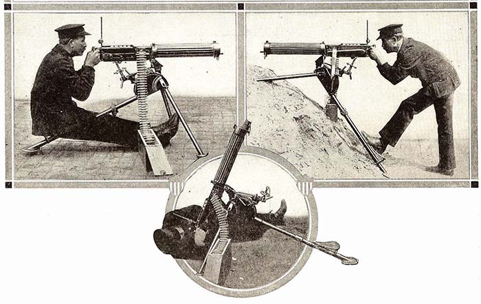
As the Maxim went through a number of improvements and refinements, starting with the Model 1901 “New Pattern” Maxim and continuing with the Model 1906 “New Light” Maxim, to the Model 1908 “Light Pattern” Vickers, commercial sales were ultimately lagging, particularly later behind the German 1909 DWM licensed commercial Maxim. Yet, the “Light Pattern” Vickers truly was innovative by eliminating weight and inverting the toggle to break upwards instead of downward. This first Vickers gun was 30% lighter than the 1906 “New Light” Maxim, weighing in at 28 pounds and exactly half the weight of the standard British Service Maxim that weighed 56 pounds. Later, due to increased efficiencies of manufacturing, the weight actually increased to 33 pounds. Still a tremendous weight reduction over the early Maxim designs.
Vickers produced a series of commercial tripods designated as Mark “B”, Mark “C”, Mark “E”, Mark “F” and finally the Mark “J”. All of them were competing against the excellent and highly practical tripod that the Germans offered with their commercial DWM Maxims. The commercial Mark “B” tripod was introduced with the 1906 “New Light” Maxim. It featured a crank handle on the right hand side that allowed the level of the gun to be lowered or raised along sliding rails. Changes were made to the Mark “B” to become the so-called “Mark C” though there is no evidence that Vickers actually designated it as such. The improvements included eliminating the curved slots in which the leg pivots traveled up and down the inside the tripod head.
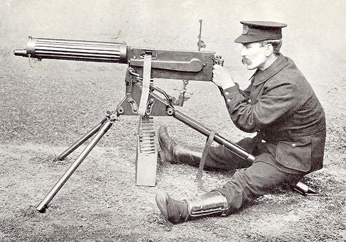
Though the Mark “B” and Mark “C” tripods were designed for the 1906 “New Light” Maxim, it was felt that the new 1908 “Light Pattern” Vickers deserved a new tripod and the Mark “E” was established. This still had the complicated and expensive to manufacture elevating mechanism that was cranked up with a handle, but the handle was now removable and used to tighten or loosen a bolt holding the slightly curved cradle that supported the gun. The Mark “E” could be supplied with or without wheels and the seat had flash holes that acted as handles on the trailing leg. The Mark “F” was another slight improvement.
All these commercial tripods as offered by Vickers were very expensive to make and ultimately few were sold. Russia bought 268 Mark “E”s and records show only 43 Mark “F”s were sold – for a grand total of slightly over 300 units. Then, Italy ordered 890 Vickers guns but refused to buy any of the expensive commercial tripods and instead had tripods made in Spain. Vickers, with the loss of those tripod sales to Italy, figured they needed to produce a new tripod, the Mark “J” that was much simpler and cheaper to produce.
The Mark “J” eliminated the expensive and complicated wind-up feature of the crank handle to level the gun. Elevation and depression was conducted by a curved cradle sliding on a curved ramp. Additionally, the front legs were adjusted by hand and gone was the crank handle. The Mark “J” was supplied commercially when World War I began with France being the largest buyer of some 2,000 guns and tripods. But, the British War Office, from January 1, 1906 onwards, wanted the heavier 56-pound Mark IV government pattern tripod for all Maxims and Vickers guns. Marks “B”, “C”, “E”, and “F” probably never exceeded 600 units. Only the Mark “J” could have possibly produced a profit for Vickers. It certainly would have made sense for Vickers to produce the Mark IV Government tripod from the beginning in 1906, but the lightweight and innovative tripod offered with the commercial German DWM Model 1909 caused concern for Vickers in the international commercial market.
U.S. Testing
Meanwhile, the United States slowly began to realize that they were way behind in arms development and inventory for their army and began a long series of tests to find a new and modern machine gun for the army as early as 1903. Up to that time, the army was still using various models of Gatling guns. Dragging on for years, these tests ultimately resulted in the adoption of the Colt Maxim Model of 1904 and then the Automatic Machine Rifle Model of 1909 (Benét-Mercié).
Then on March 16, 1913, the Board of Ordnance & Fortification held a meeting to consider the adoption of a new type of machine gun and on September 15, 1913 the Board convened for the competitive test of the machine guns at Springfield Armory. Seven makes of automatic machine guns were submitted but only three were considered worthy of consideration: the Lewis gun, the Automatic Machine Rifle Model of 1909 and the Vickers gun. The Board concluded, after careful consideration of the data collected, together with the knowledge of the suitability of the various designs of machine guns gained by observation during the test, that the Vickers machine gun and the Automatic Machine Rifle Model of 1909 were the only two types sufficiently serviceable to warrant their entry into a further field test.
U.S. Colt Vickers Model of 1915
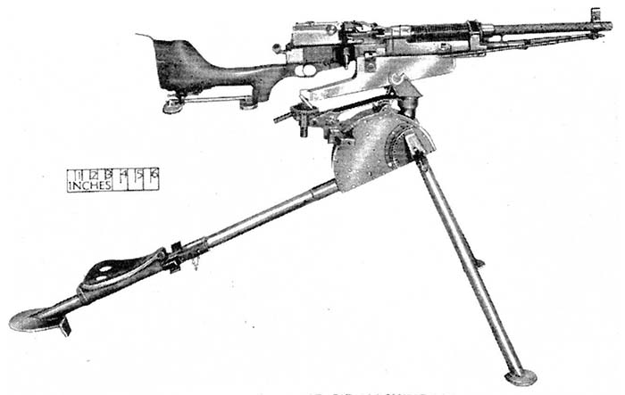
The Vickers machine gun, as a result of these tests and subsequent field tests held in 1914, was adopted as the approved type for the Army, upon the unanimous recommendations of the Board and designated as the Model of 1915. This was based upon the test results of the three Vickers sent from England along with three Mark “J” tripods. In 1915, funds were made available and were used in making a contract for 125 Vickers guns with Colt’s Patent Fire Arms Manufacturing Company. The machine gun situation rested at this stage until the latter part of 1916 when additional funds were made available, and on December 16, 1916 a further order for 4,000 Vickers machine guns and tripods with 960 pack outfits was placed with the Colt’s. At this point, the U.S. Model of 1915 tripod was to be the standard government issue tripod for the U.S. Model of 1915 Vickers machine gun.
Up to the time of the entry of the United States into the European War on April 6, 1917, the Ordnance Department had been able to purchase, with money available for this purpose, 665 Benét-Mercié Machine Rifles, (the adopted service arm of 1909) and 287 Maxim machine guns, Model of 1904, all of which were issued to the Regular Army and the National Guard. In addition, a total of 353 Lewis machine guns, chambered for the British caliber .303 ammunition, had been purchased from the Savage Arms Corporation during the summer of 1916 for issue to the troops that had been called to the Mexican Border, and who had not previously been supplied with machine gun equipment.
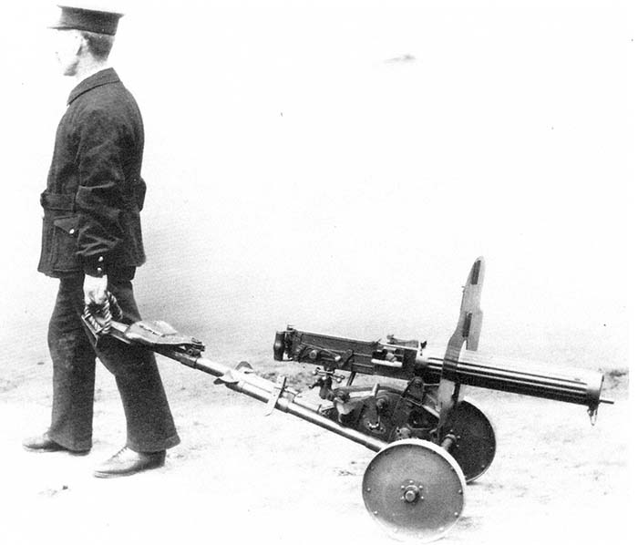
Though Colt’s was under contract for 4,125 Vickers guns, by mid 1917, none had yet been made. Colt’s was busy making other arms and fulfilling other contracts and had difficulty in setting up the factory to produce the Vickers. Colt’s originally thought they could make final delivery of their first contract of 125 guns by May 10, 1917; but it was not to be.
Because Colt’s was running behind schedule, the War Department recommended that an additional 2,500 Vickers machine guns be bought from Britain since they should be immediately available. On December 16, 1916, the Vickers Company was contracted to furnish, among other things, 4,000 Automatic Machine Gun Tripods Model of 1915 (British model Mark “J”); the deliveries of tripods were to commence in June, 1917, and were to be completed November 16, 1917. Vickers replied that fixtures for the above items would not be ready before September, 1917 and that deliveries of tripods would not commence until October, 1917 and the final deliveries of guns would be November, 1917. This would give a considerable number of guns on hand without tripods. This was primarily due to Vickers in war-time production of the government Mark IV tripod.
Springfield Armory had made up some Model of 1915 tripods for the first 125 gun Colt’s contract but was in no position to go into full scale production and the final decision on the type of tripod was uncertain due to production and availability problems. On June 19, 1917, the Ordnance Office sent a letter to Colt’s stating that their proposal to deliver the Mark IV tripod with the first 2,500 Vickers guns, to be delivered under the contract for 4,000 was approved. This letter requested them to proceed with the manufacture of these tripods in order to meet the delivery dates submitted. The end result was that the U.S. Army Ordnance Department adopted the British pattern Vickers as the U.S. Model of 1915 with the British pattern Mark “J” tripod, but ultimately ended up with the British pattern Mark IV tripod which was holding up very well under the harsh conditions of World War I. Since Vickers could only supply the Mark IV tripods for their orders, The Mark IV became the standard and the U.S. Model of 1915 Tripods faded into obscure history.
The Manual
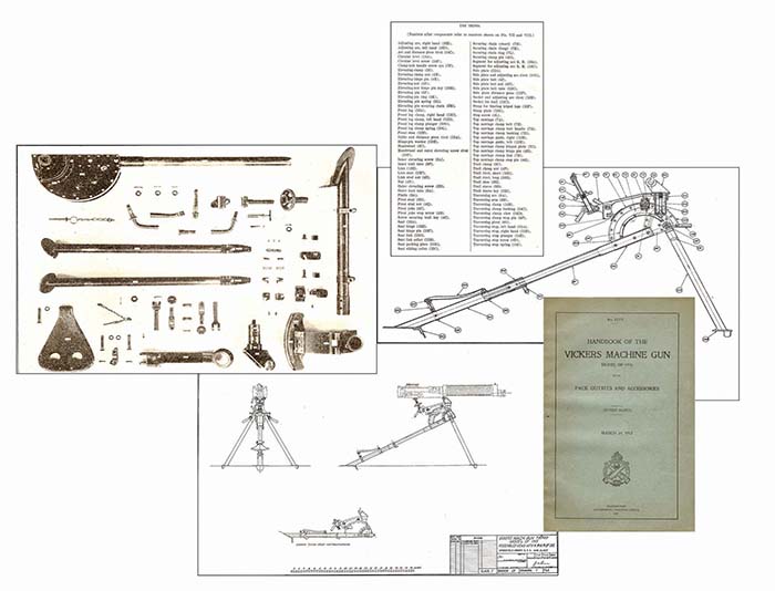
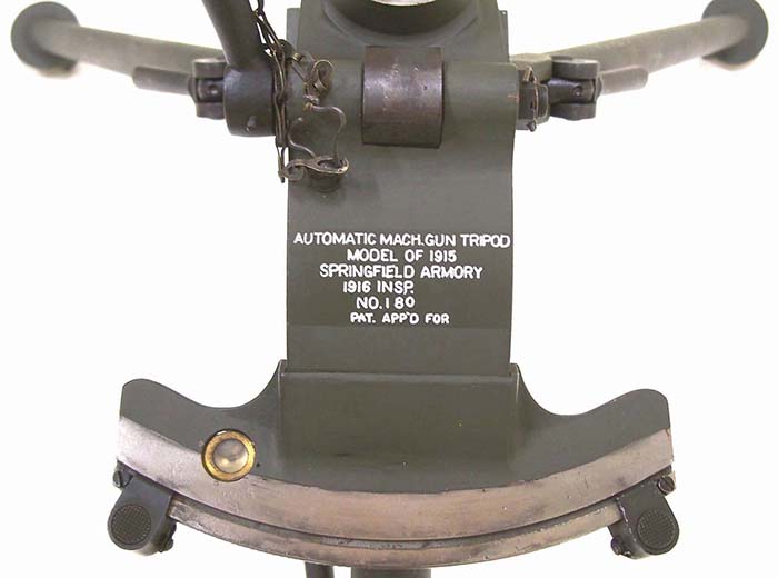
It is interesting to note that the War Department Office of the Chief of Ordnance published manual No. 1775, Handbook of the Vickers Machine Gun Model of 1915 with Pack Outfits and Accessories on March 19, 1917. These manuals were actually put together before the gun even went into production and was pretty much based upon the British version. As such, the manual shows and details the Model of 1915 tripod instead of the Mark IV that was actually adopted, manufactured and used. Additionally, in the detailed description of the tripod that follows below, the text actually describes the British Mark “J” tripod rather than the Model of 1915 tripod as made by Springfield Armory even though the Springfield Armory and exploded parts photograph are of the Springfield Armory model. While the U.S. Model of 1915 tripod is a copy of the British Mark “J”, it is not an exact copy.
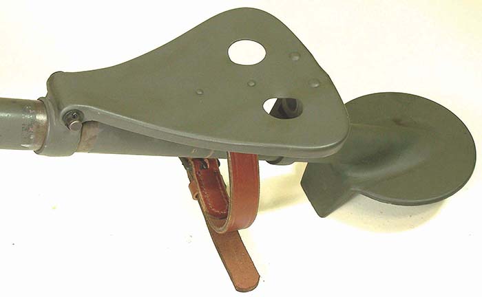
Some differences are noted here. The manual states, “A pair of leg clips fastened to the outer tube (in front of the seat) serves to bind securely to the trail the front legs when the tripod is folded.” The Model of 1915 Tripod has a metal loop welded underneath the seat that holds a leather strap that is used to bind the front legs to the trail when folded. There are no metal clips to hold the legs. Additionally, the manual fails to mention the addition of a circular level bubble located on the left side of the traversing arc that is included on the Model of 1915 but not the Mark “J.”
Description of the Tripod
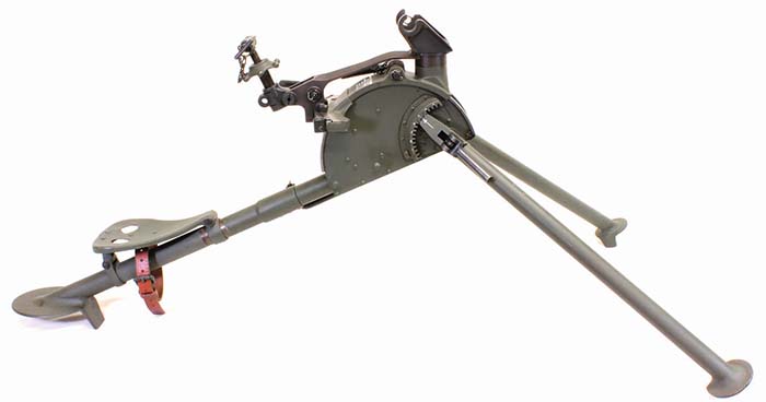
The tripod consists of the following principal parts: Front legs, trail, seat and seat bracket, pintle and pivot, top carriage, body, traversing mechanism and elevating mechanism.
The Front Legs
The front legs consist each of a short length of drawn steel tubing carrying at the upper end the link by which it is attached to the adjusting arc and at the lower end a flattened shoe. One end of the link is turned to fit snugly in the bore of the tubing and riveted thereto in two places. The upper end of the link terminates in three teeth which fit into a circular rack when adjusted for firing. When it is desired to fold the tripod for transportation or to extend the front legs forward in carrying by hand, the slot in the link permits the clamp to be loosened from its seat on the drum and the teeth to be disengaged from the adjusting arc, swung around, reengaged, and clamped.
The Trail
The trail consists of two lengths of steel tubing, called the outer and inner trail tubes. The inner tube fits into and is riveted to a socket, which is also riveted between two semicircular side plates, and at its front end carries two adjusting arcs for the front legs. The outer trail tube forms the trail clamp and holds the attachment for the seat.
The inner tube is turned to fit closely the bore of the outer tube, in which it has a sliding motion, this motion may be stopped and the inner tube clamped in any position by means of the trail sleeve clamp which is riveted to the top end of the outer tube. The sleeve is split for a short distance back from the end, so that by tightening the clamp the lugs are brought nearer together and the inner tube firmly gripped.
The key inserted in the trail sleeve works in a longitudinal slot cut in the surface of the inner tube on the underside and prevents the tube from turning. To the rear end of the outer tube is attached a shoe similar to those on the front legs. This construction of the trail permits adjustment of its length to uneven surfaces and shortening to a minimum length for transportation. A pair of leg clips fastened to the outer tube serves to bind securely to the trail the front legs when the tripod is folded.
The Seat
The seat is of sheet steel pressed to shape. Its front end is pivoted to fit the seat sliding collar which slides on the trail tube. The rear end is pivoted to the seat link, which in turn is pivoted to the seat link collar attached to the outer trail tube.
The seat link collar is of steel and riveted near the end of the outer tube. On the underside of the seat are two lugs of the hinge drilled and riveted to it, the action of which is described below. For transportation the seat slides forward by means of the seat sliding collar to which it is pivoted. The rear of the seat folds down close to the trail and the top of the seat link rests on the trail. In action the seat is slid backward and automatically stops by the contact of the seat link with the seat link collar.
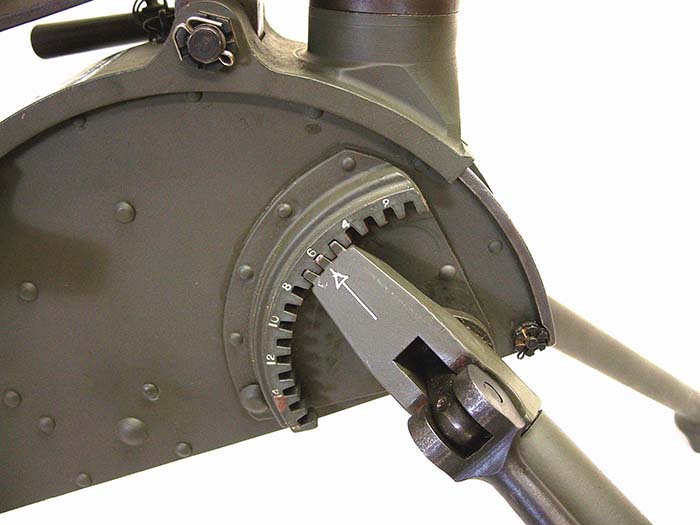
The Pintle
The pintle is a hollow steel forging which furnishes the points of attachment for the legs and trail, the pivot for transverse movement of the gun and top carriage, and the seat for the traversing arc.
In the rear of this casting are machined two surfaces inclining outward to which the traversing arm is riveted. The upper end is turned to form a bearing for the top carriage, traversing pivot and yoke. The rear end of the traversing arm furnishes pivot bearings for the elevating nut, while on the underside is the clamp for the traversing arc, the rear edge of which is turned to an arc struck from the center of the pintle axis and fits into a corresponding groove in the rear of the traversing arm, thus preventing the latter from jumping. The top surface of the seat is machined to form a flat bearing surface for the rear ends of both the top carriage and the traversing arm.
The top and front of the pintle is turned to form a vertical bearing for the top carriage and traversing arm. In the upper part of the bearing is pivoted the yoke.
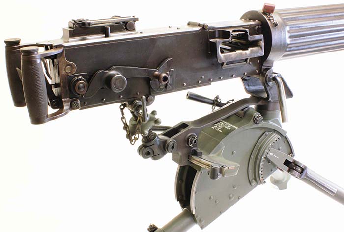
The Top Carriage
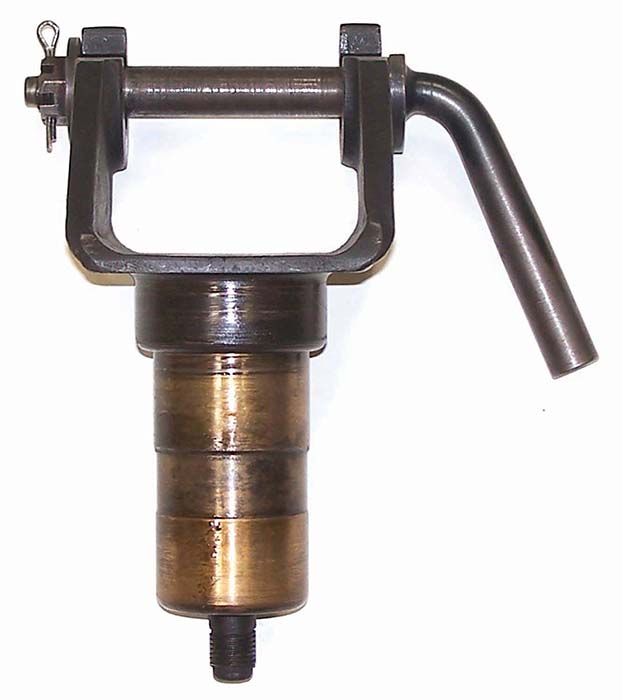
The top carriage is a steel forging consisting of a hub bored out to fit over the pintle and an arm projecting downward and to the rear, to which the traversing arc is riveted. The arm is also gibbed to the top carriage guide by means of the groove engaging the circular lip on the latter. On top of the hub is the pivot yoke drilled and slotted transversely for the trunnion pin. The gun rests between the cheeks of this yoke supported by and rotating on the trunnion pin. One end of this pin is bent to a sharp angle to form a handle, while the other is threaded to receive the adjusting nut. The cheeks of the pivot yoke are reamed out and slotted to the size of the ends of the pin. On mounting the gun the pin is dropped through the slots on the pivot yoke and secured by rotating the handle, thereby tightening the cam.
The web at the rear of the top carriage is cut away just in rear of the hub for the top carriage clamp link, and a hole is drilled through the horizontal web for the top carriage clamp bolt, the head of which is fitted with a lever handle. The eccentric portion of the clamp bolt is fitted with a bushing into a link connecting to a hinged plate. By rotating the clamp bolt this plate is raised to engage the notches under the top carriage guide, thereby locking the top carriage to the body.
The Body
The body consists of the side plates, top carriage guides, trail socket, distance pieces and adjusting arcs of the front legs.
The Traversing Mechanism
The traversing pivot is drilled for the passage of the pivot stud and counterbored slightly as a seat for the shoulder on it.
The traversing arm is a steel casting to one en of which is riveted the pintle and rests upon the shoulder formed at the base of the latter. Slightly in rear of this bearing a curved slot is cut, through which the traversing arc passes, and in rear of this slot the arm is bent downward. At the rear end is formed a yoke in which is pivoted the elevating nut.
In front of the elevating nut is fitted the traversing clamp, which consists of a claw, a bushing and clamp handle. By swinging the handle one way or the other the claw engages the under surface of the traversing arc thereby clamping the arm stationary with the traversing arc. On each side of the traversing arm a traversing stop is fitted to the traversing arc. This stop is fitted with a plunger, a spring and a screw and hooks over the rear of the traversing arc. By pinching this stop between the thumb and forefinger of either hand it may be disengaged and set at any desired position on the traversing arc. When these stops are placed on the extreme ends of the traversing arc, the traversing arm may be swung 22.5 degrees either side of center. By releasing the elevating gear an all round training may be attained but without any clamp.
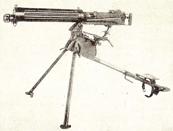
The Elevating Mechanism
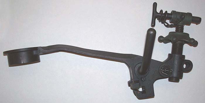
The elevating mechanism consist principally of the outer elevating screw, the inner elevating screw, the elevating nut, hand wheel, the elevating clamp, the elevating nut pin and the elevating pin.
The outer elevating screw is a steel cylinder, on which is screwed at the upper end the handwheel, with six knobs, with which the screw can be turned by hand. A right-hand screw thread is cut on the exterior of the body and a left-hand thread is cut for a short distance on the interior of the body. The remainder of the bore is reamed out to a diameter large enough to clear the inner screw when in place.
The inner elevating screw is a steel forging, at the upper end of which a T-shaped head is formed, which is drilled transversely. This head fits between lugs on the bottom plate of the gun and is secured at one end which is held in place by riveting.
On the body of the screw is cut a left-hand thread corresponding to that on the interior of the outer screw. The lower end is drilled and tapped axially for a stop screw, which, by closing the end of the thread, limits the upward movement of the inner screw when it comes in contact with the bottom of the interior thread in the outer. The elevating nut is a long nut, carrying at its lower end a lug drilled to take the elevating-nut pin by which it is hinged to the top carriage and at its upper end a second lug for the elevating clamp. The bore of the nut is threaded for the outer elevating screw for its whole length. The threaded part is slotted longitudinally through the center of the clamp lug. One side of the latter is reamed to take the body of the clamp and the other is threaded. The clamp itself consists of a bent handle and a body partly smooth and partly threaded. It is inserted through the reamed portion of the lug on the nut and screws through the threaded portion, being kept in place by a collar and pin on the projecting end. By screwing in the clamp still further the two portions of the lug are brought closer together, thus causing the nut to grip the outer elevating screw tightly and prevent any movement of the latter.
As the inner elevating screw is prevented from turning by its attachment to the gun and the elevating nut likewise by its attachment to the carriage, it follows that rotation of the outer screw will cause it to move either up or down in the nut and at the same time force the inner screw in the same direction. The elevating mechanism gives a range in elevation of 16 degrees.
By disengaging the T-head of the elevating screw from the bottom cover plate the gun may be swing around a complete circle. By swinging it around 180 degrees the gun may be elevated to 75 degrees, but without any elevating clamp.
| This article first appeared in Small Arms Review V17N1 (March 2013) |


