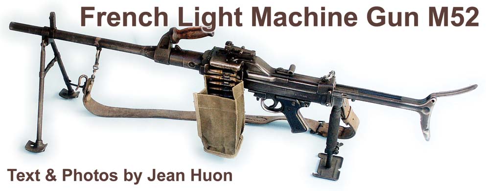
A.A. 52 7.5mm light machine gun with opened bipod and link bag. (MAT).
By Jean Huon
After 1945, the French army was equipped with a wide variety of materials (armament, uniforms, helmets, equipment, radios, vehicles, airplanes, boats, etc.). In the field of armament, various makes and models could be found that included French, American, English and German weapons. Several programs of harmonization were undertaken and, for machine guns, several models were developed between 1948 and 1952 that included:
- the Ateliers de Mulhouse that developed a weapon derived from the MG 42,
- the Manufacture Nationale d’Armes de Saint-Etienne that developed a gas action machine gun, and
- the Manufacture Nationale d’Armes de Châtellerault that built a weapon with a semi-rigid locking mechanism.
Each one of these weapons was envisioned to be fed by link, box magazines, or both. Additionally, each gun was developed in a light and heavy model for the French 7.5mm cartridge or American .30-06.
Ultimately, the weapon produced by MAC was retained and adopted on August 22, 1952 under the name of Arme Automatique (Automatic Weapon) Model 1952; or A.A. 52. Only the model in 7.5mm supplied with links was retained though variations of this model were also developed. The first guns were delivered in February 1956. In 1962, a version being able to fire the 7.62mm NATO cartridge was developed and adopted under the name of A.A. 7.62 N-F 1. Following the closing of Châtellerault, manufacture was transferred to the Manufacture Nationale d’Armes de Tulle in 1967-68. MAC produced approximately 35,000 A.A. 52s in 7.5mm and 17,000 A.A. 7.62 N-F 1 before closing. An enlarged version of A.A. 52 in .50 caliber was studied between 1956 and 1959, but was not adopted.
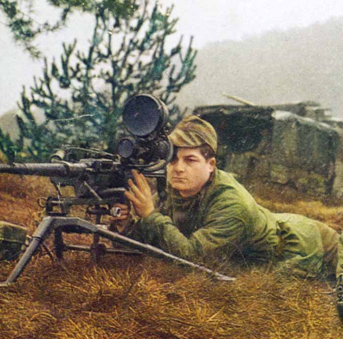
Description
The receiver and the majority of parts of the A.A. 52 are made of stamped sheet metal. Only the barrel and the bolt are of machined steel. The weapon works with a semi-rigid locking mechanism and the opening is delayed by an inertia amplifying lever.
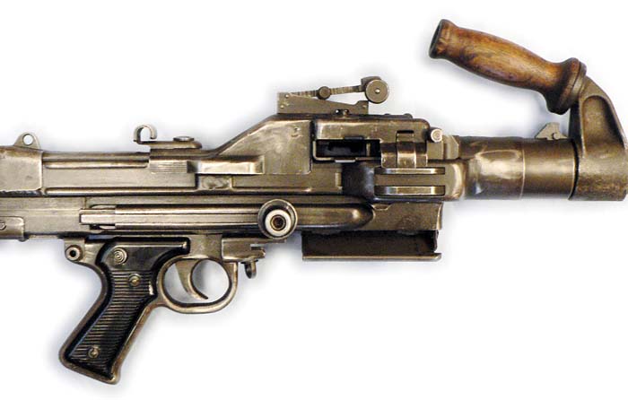
The receiver is of a rectangular pattern with a cover that includes the feed mechanism at the top. The cocking lever with slide is placed on the right. The trigger mechanism and pistol grip are under the frame. The ejection port is under the frame and has a folding cover. The bolt consists of the bolt carrier with a movable head and an inertia amplifying lever. The weapon utilizes a telescopic stock with an articulated butt plate.
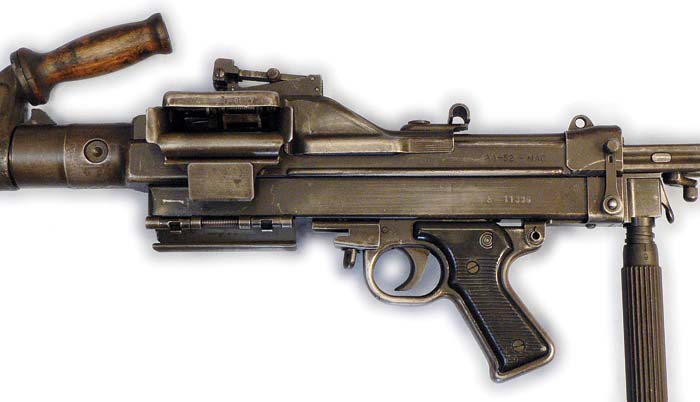
The removable and interchangeable barrel is fitted with a handle that is also used for transport of the weapon. The barrel has a fluted chamber and the 7.5mm barrel has four right groves with a pitch of 240 mm. The 7.62mm barrel has the same groves but with a 300 mm pitch.
A safety push button is installed on the trigger mechanism. There is no selector and fires in full auto only.
The sights consist of a folding front sight and a U-notch rear sight adjustable from 200 to 2,000 meters. After 1962, they received phosphorescent pellets for night shooting.
Feeding can be made with the continuous German Gurt 34 link or French designed disintegrating links. Both the feeding mechanism, trigger device and pistol grip are copies of the MG 42.
Preparing to Shoot
With the bolt forward in the closed position, introduce the flat end of the link from left to right in the feed-way until a catch occurs. Pull back the cocking lever. The bolt is retained by the sear and the recoil spring is compressed. Push the cocking lever to the front. If the link has no flat end, remove the first two cartridges (in the case of a non-disintegrated link), open the feeding cover, cock the gun, place the first link on the right side of the feed plate and close the cover.
Operation
The shooter presses the trigger, which lowers the hook of the sear and allows retraction of this part. Under the action of the compressed recoil spring, the bolt group is projected forward. As the first cartridge is pushed from the link (direct introduction), it meets the depressor and is introduced into the chamber. At the same time, at the end of the forward movement, guided by the higher slope of the bolt carrier, the supply lever oscillates and permits the feed driving pawl to go from the right to the left. With the bolt head in place, the inertia amplifying lever is in its housing. The bolt carrier finishes going forward and the firing pin then strikes the cartridge primer. If the bolt is not completely closed, the firing pin cannot strike the cartridge.
Upon firing, the gas pressure being exerted both on the bullet and the case makes the head of the bolt undergo a thrust backwards. The small branch of the lever is in contact with the bolt and the large branch takes support against the frame. The lever transmits to the bolt an impulse much faster than that which it received from the bolt head. It works like an amplifier of inertia and causes a delay with the opening. The bolt carrier then involves in its movement the bolt head and the lever. As the bolt starts its rear movement, the empty case is extracted from the chamber and when it meets the two lugs of the feed cover, it is ejected downwards. The feed lever oscillates and the driving pawl pushes the link that moves and advances to the resting pawl (from left to right). This causes the ejection of the link. With the bolt to the rear and the recoil spring compressed, the bolt will then move back forward and the cycle is renewed until the gunner ceases its action on the trigger. At that time, the bolt will be retained in the rear position by the sear.
To operate the safety, it is necessary to push its transverse push-button towards the left. This locks the trigger.
To unload and release the link, it is necessary to cock the weapon, then apply the safety, open the top feed cover and remove the link. (Look to visually confirm that no cartridge is in the chamber. Push the safety to the right and let the bolt come gently forward while assisting it with the cocking lever.
Changing Barrels
There are two types of barrel retainers. In the retainer of the first type, use the disassembly extractor tool or the point of a cartridge to push the retainer backwards. Using the carrying handle, turn the barrel 1/6th of a turn to the right and extract it toward the front. To install a new barrel, insert it with a 1/6th turn to the left of the axis, push it and turn to the right until the retainer ensures its locking.
Retainers of the second type are installed on weapons carrying a serial number higher than A 34166. Push the retainer with the hand while pressing on the lever. Then use the carrying handle, turn the barrel 1/6th of a turn to the right and extract it toward the front. The movements to be carried out for its reinstallation are the same as above though it is necessary to maintain the retainer retracted as long as the barrel is not in place. It is possible to see if the barrel is correctly engaged if the white feature painted behind the retainer is visible.
Accessories
Sighting:
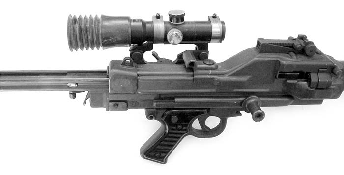
- day scope APX L 806,
- day/night scope with infra-red equipment DIPT 8A,
- Sopelem night scope, with light amplifying,
- rubber cap for scope,
- scope mount.
Shooting:
- light or heavy replacement barrel
- replacement barrel for blank shooting,
- bags for ammunition links,
- device to adjust tank machine gun No. 1, exactly parallel to the tank gun.
Replacement box placed in the fabric maintenance bag:
- one fixing key,
- one trigger guard axis,
- two extractor springs,
- two extractor push rods,
- two extractors,
- one amplifying lever.
- four strikers.
Maintenance bag M 1950 or 1954:
- a cartridge extractor,
- a pistol grip pin,
- a tool to dismount the extractor;
- a hook-ejector;
- a cleaning-rod in three elements;
- a silk brush to clean the barrel,
- a brush to clean the chamber,
- a flat brush;
- a metallic oil can M 1949 or plastic M 1962.
Transport:
- a leather strap for the light machine gun;
- a fabric protective cover for the weapon (light or heavy),
- a fabric case for replacement barrel;
- haversacks for the transport of maintenance material, replacements parts or ammunition.
Supports:
- bipod for light version. Two variations exist: first model with tubular legs, second model with U-shaped sheet metal legs,
- removable monopod rear support for light version, similar to the model used with the Châtellerault M 24-29 LMG,
- U.S. M2 tripod with special mounting MF 52 (Modified French 1952) for the heavy version. It is fitted with an elastic recoil device.
Variations
- light machine gun A.A. 52 or A.A. 7.62 N-F 1, model with short barrel, fitted with a stock, folding bipod and a rear monopod and hook for link bag
- infantry heavy machine-gun A.A. 52 or A.A. 7.62 N-F 1, model with long barrel, fitted with a stock and mounted on tripod U.S. M2 MF 52 and hook for link bag,
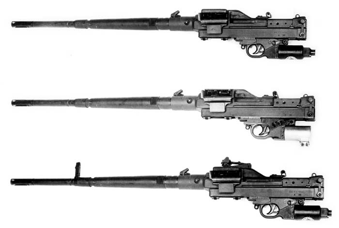
- Tank C 1. Long barrel without carrying handle, no sights, no stock, no hook for link bag, manual or electric firing device (version A is not waterproof, version B is waterproof).
- Tank C 2. Long barrel without carrying handle, front and rear sights, can receive a stock but no rear monopod, special cocking lever to be used in reduced space like tank turret, no ejection port cover, manual firing device.
- Aircraft No. 2. Long barrel without carrying handle, no sights, can receive a stock but no rear monopod, manual firing device.
- Aircraft No. 3. Same as Tank No. 2, but with standard cocking lever, manual or electric firing device (version A is not waterproof, version B is waterproof).
- Aircraft No. 4. Similar to the preceding one but with front and rear sights and hook for link bag
The A.A. 52 or A.A. 7.62 N-F 1 can be installed in a turret or individual support for armored vehicles or by twin in a pod for aircraft or helicopter.

Disassembly/Reassembly
Open the feed cover and remove the link. Cock the gun and visually check that the chamber does not contain a cartridge. Let the bolt return forward slowly by using the cocking lever to retard movement. Press on the stock retainer and remove the stock. Unscrew the fixing key and leave the rear block. Pull the cocking lever backwards. Leave the recoil spring and its rod. Remove the bolt by slipping it backwards. Remove the axis pin of the pistol grip block to release it from the frame. Open the feed cover and the feed plate at 90° to the top and remove the axis pin which connects them with the frame. Remove the bolt head, the firing pin and the inertia lever from the bolt carrier. The reassembly is carried out in the inverse order. Be careful of the exact position of parts of the bolt and the feeding device.
12.7mm Machine Gun Type M.A.C. Using the same mechanism as the A.A. 52, several prototypes of a heavy machine gun using the same ammunition as the U.S. .50 caliber M2HB were conducted between 1956 and 1959. This model is like an enlarged version of the smaller caliber machine gun and is designed in the same manner. The frame has no rear block and the dismounting of the gun is slightly different. The rear sight is graduated in hectometers from 0 to 30 and the front sight can be folded.
Feeding is carried out with metallic links:
- American disintegrating links,
- French designed disintegrating links similar to, but larger than, those used with the A.A. 52,
- French designed non-disintegrating link; an enlarged copy of the Gurt 34.
The barrel is removable and interchangeable and has no carrying handle. The 12.7mm automatic weapon has a particular trigger mechanism and several variations of it exist. On the MAC 56, two rear handles are fixed to the frame and an axial trigger pushed by the thumb allows the firing as on the Browning U.S. M2HB machine gun. The barrel has a fork truncated flash hider. For the MAC 58, the trigger mechanism is prolonged by a conventional pistol grip. The safety is operated by a lever on the left side. The barrel has a cylindrical flash hider with lateral holes. Both weapons are fitted with a recoil absorber. A French designed mount, with an elastic recoil device, allows the use of the U.S. M3 tripod or any vehicle mount initially intended to receive the American weapon. The 12.7mm guns were put to test a few times, but the model was not adopted because it did not make any particular improvements compared to the same guns in this caliber already in service.
Conclusion
The French automatic weapons A.A. 52 and A.A. 7.62 N-F 1 are reliable and robust weapons. The light version can be used up to 800 meters and the heavy version has a range of 1,200 meters. The receiver has an estimated life of 60,000 rounds. It started to be used in Algeria at the end of the 1950s and continued to be equipped with the French infantry until the beginning of the 21st century. They have now been replaced by the F.N. MINIMI. They continue to be used on armored vehicles and ships. The new Caracal helicopters, which are in service in the Air Force, are equipped with MAG machine guns.
| A.A. 52 Light | A.A. 52 Heavy | |
| Caliber: | 7.5mm | 7.5mm |
| Ammunition: | 7.5 x 54 | 7.5 x 54 |
| Overall length: | 1.145 m (45.08 inches) | 1.245 m (49.02 inches |
| Length (stock retracted) | 0.980 m (38.58 inches) | 1.080 m (42.52 inches) |
| Barrel length: | 0.500 m (19.69 inches) | 0.600 m (23.62 inches) |
| Weight of weapon: | 9.150 kg (20.17 lbs.) | 10.500 kg (23.15 lbs.) |
| Weight of tripod: | 10.600 kg (23.37 lbs.) | |
| Cyclic rate of fire: | 800-900 rpm | 800-900 rpm |
| 12.7 mm Type MAC 58 | |
| Caliber: | 12.7mm (.50) |
| Ammunition: | 12.7 x 99 (.50 Browning) |
| Overall length (with flash hider): | 1.628 m (64.09 inches) |
| Overall length (without flash hider): | 1.000 m (39.37 inches) |
| Weight of weapon: | 26.740 kg (58.95 lbs.) |
| Weight of tripod: | 20.655 kg (45.54 lbs.) |
| Cyclic rate of fire: | 600 rpm |
| This article first appeared in Small Arms Review V11N10 (July 2008) |


