By Robert G. Segel
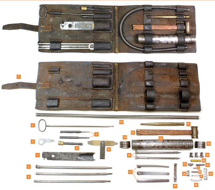
The rare and seldom encountered tool and spare parts wallet is made of brown cowhide leather that folds in half and is secured by a single leather strap attached by a nickeled steel buckle. The wallet is carried in a canvas waist pouch that attaches to a waist belt.

The contents of the tool and spare parts wallet are as follows:
1) Brown cowhide leather wallet with stitched in loops and tool holders.
2) White metal cartridge case remover with claw end.
3) Punches (2), one 0.077 in. (2 mm) and one 0.188 in. (4.5 mm).
4) Ruptured case extractor tool.
5) Unidentified tool (not in manual).
6) Standard folding type screwdriver.
7) Gas regulator adjustment tool. One end is to remove, install and adjust the gas cylinder. The other end is to extract a broken firing pin.
8) Scraper attached to end of cleaning rod segment.
9) Cleaning bore rods (2).
10) Operating spring. 16 3/4 in. long x .38 in.
11) Brass drift or cheater bar.
12) Brass hammer with 2 oz. head with wood handle.
13) Spare parts can (tinned steel). The can is 6 in. long (15.24 cm) and 1 in. (25.4 mm) wide. Note that the can is made up of two sections indicated by a raised rib that can be seen on the outer tube with a steel disk in the interior at the point of the rib that provides a partition. The left hand side of the container as shown here is 4 3/4 in. long (12.065 cm) and the right hand side is 1 1/4 in. long (3.175 cm). The following list of items numbered 16-18 fit in the long left hand side of the tube and items numbered 19-28 fit in the smaller right hand side of the tube.
14) Screw cap for left side of spare parts can.
15) Screw cap for right side of spare parts can.
16) Firing pins (2).
17) Extractor springs (3).
18) Bolt spring.
19) Extractors (3).
20) Threaded brass tube for attaching to bore rods to attach cleaning jag. It is 1 in. (26 mm) long and 0.23 in. (6 mm) in diameter with different internal threads on each end: 0.12 in. (3.2 mm) one side, 0.144 in. (3.6 mm) on opposite end.
21) Feed rack plunger.
22) Feed housing follower stop.
23) Coil spring 29 x 9.5 mm (trigger sear spring)
24) Coil Spring 14 x 7.5 mm (back plate buffer spring)
25) Coil Spring 8 x 3 mm (gas regulator adjustment spring)
26) Coil Spring 15 x 4.4 mm (feed rack plunger spring)
27) Coil Spring 20 x 4.3 mm (undetermined)
28) Coil Spring 28 x 4.4mm (oil reservoir applicator spring)
| This article first appeared in Small Arms Review V19N7 (September 2015) |


