By Walter F. Hern
I bought my Vickers gun a couple of years ago. From the first day I took it to the range it has run flawlessly. Unfortunately it also suffered from atrocious accuracy. At 100 yards only 1 in 10 shots would hit a cardboard silhouette target. The main cause was readily apparent, the pins that secure the gun to the tripod, and their corresponding holes in gun and tripod, were excessively worn. To use a bit of fancy modern military terminology, the gun to tripod interface was as loose as a goose! Every time I fired a burst, the gun would be bouncing around on the pins. No wonder it only had “minute of backstop” accuracy.
In military training these guns were moved and deployed a lot more than they were fired. Every time the gun was moved the pins securing the gun to the tripod were pulled and replaced. Years of sliding steel pins into the steel of gun and tripod caused wear to both. The Vickers gun is more susceptible to this kind of wear because two removable pins are utilized to secure the gun to the tripod each time it is set up. The front pin attaches the gun to the crosshead and the rear to the elevating gear.
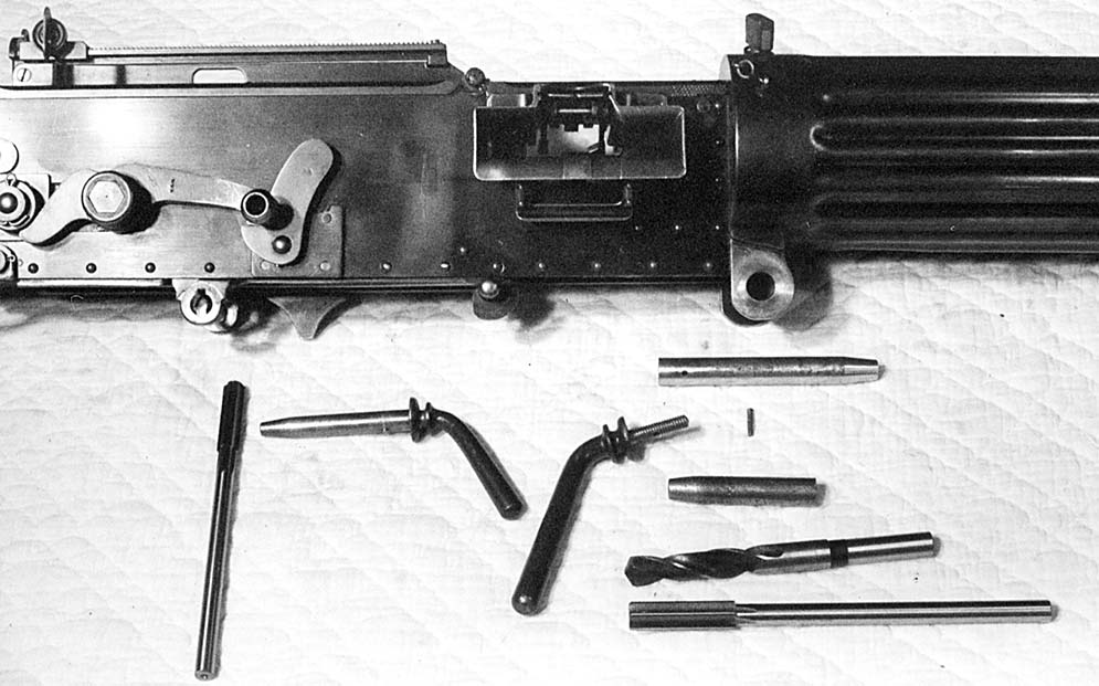
The obvious solution was to ream the holes true and make new pins to fit. The first step was to take measurements to find out how much wear was in the various holes. On the front, gun-to-crosshead, connection, the gun fits in between the sides of the crosshead. The brass crosshead has steel bushings fitted, with the holes for the pins in these bushings. The hole in the left crosshead bushing features a keyway at the bottom, and a recessed groove around its circumference on the gun side of the bushing. This is to accommodate the “feather.” The feather is a small pin going through the main pin and projecting about 1/8” from one side. The feather on the front pin serves two functions. Its main function is to keep the main pin from working out under vibration. When the pin is inserted, the feather goes in through the keyway, and turning the handle down positions the feather in the groove of the bushing. The width of the feather also serves to take up any side-to-side play of the gun between the sides of the crosshead. The gun has tabs extending below the receiver, connected with a tube. The hole for the pin goes through the tabs and tube. The pin goes through the left side of the crosshead, through the tube in the gun, and then out through the right side of the crosshead. The left crosshead bushing had more wear than the right one, and the left side of the tab/tube on the gun had more wear than on the right side. The wear was not even, and the holes were egg shaped. The diameters of the holes were measured with an electronic caliper. The hole in the left bushing of the crosshead measured from .577” to .589” depending on the location of the measurement taken, the key slot for the feather complicating things a bit. The hole in the right bushing of the crosshead measured .573”top to bottom and .571” side to side. The hole through the gun on the left side measured .582” top to bottom and .5755” side to side and on the right side, .5785 top to bottom and .575 side to side. The pin, measured .561” in diameter for most of its length.
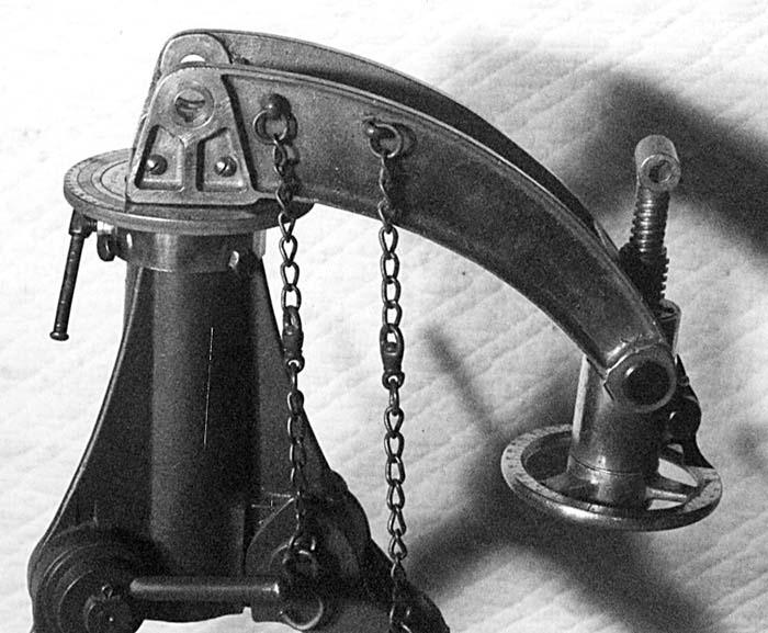
The rear pin attaches the gun to the elevating screw. The gun has a tab on either side with holes in them. The top of the elevating screw has a “T” shape to it. The top of the “T” goes between the tabs and is in the form of a tube to accept the pin. This pin goes through from right to left. The feather on this pin passes through a keyway on the right hand mounting tab of the gun, and when the pin is turned, engages a groove in the elevating screw “T.” The wear was greater, naturally, to the hole on the right side of the gun. Measurement ran from .4575” to .4585”. The left hand hole measured .456.” Since the top of the elevating screw can rotate, wear was not concentrated on one side. The hole through it measured .451” from side to side, and .452” top to bottom. The pin measured out at between .444” and .448”.
Once I had the dimensions, the next question was to decide what diameter to ream the holes. On the front pin’s set of holes, the largest dimension measured was the left hand hole in the crosshead bushing at .589”. 15mm has the decimal equivalent of .5906” This was large enough to true out the entire group of holes but, not require the removal of excessive amounts of material anywhere. This was also a standard size reamer.
For the rear set of holes, the right side of the gun had the one with the most wear. It measured .4585” Since the pin would be lathe turned, I decided to ream to .4590”, which is a non standard size.
Why did I select to go to sizes just large enough to true up the holes and not much larger? There were two reasons. At some time in the future, I may need to ream again, and, secondly, if a mistake was made while machining, there would still be enough material to correct things.
Machine tool reamers are not something you generally find at the corner hardware store. My friend with the machine shop had a catalog for Rutland Tool in Whittier, California (800-289-4787). These folks put out a phone book sized catalog that has virtually any tooling your heart could desire. Let’s discuss tooling a little bit. When making holes in metal, a reamer will give you a smoother finish and a more true and accurately dimensioned hole than a twist drill bit. In production work, the desired holes are drilled undersize and then reamed to the final dimension. When discussing holes smaller than 1/2” There is a wide variety of drill bits available. You can get them in increments of 1/64 th (.015)of an inch. Then there are the Number and Letter series drills. Many of these fall in between the 1/64th intervals. There are also Metric drills, though these do not come in the wide variety of sizes “Inch Pattern” drills do. Once 1/2” is reached, things dry up a bit. Size increases of 1/64” intervals are about it, unless you can use a metric size. In my case, 15mm (.5906”) would fit my need for the front pin and was a standard size reamer in the catalog. Since the hole in the mounting fixture on the gun had enough variation in diameter from one side to the other, I also picked up a 37/64 (.578”) drill bit to bring things to a more uniform diameter before running the reamer through. Reamers up to 1/2” were available in 1/1000” increments. For the rear holes I picked one that was .4590. Because these cutters would only be used once or twice, there was no need to get expensive carbide cutters. High Speed Steel would be more than adequate. The 37/64 drill bit cost me $7.11, the 15mm reamer $24.24, and the .4590 reamer $17.50. All together, with shipping, $53.75 covered tooling costs.
The work on the holes in the gun was done on a small milling machine. The gun was stripped of all the internal parts to bring the weight down to something manageable. Masking tape was applied to keep the finish from being scratched. The gun was secured to the table of the milling machine with stepped hold downs and bolts. These were tightened just enough to secure the gun. Care was taken to not warp the receiver. The table of the milling machine can be moved in and out and back and forth to position the hole to be trued at exactly the right spot. The water jacket, which was hanging out in space, was simply supported with a camera tripod. The front hole with its tube was done first. The 37/64 drill bit removed only a small bit of steel, the then a pass with the 15mm reamer trued things up and left an almost polished surface. After repositioning the gun, the two rear holes were done in one pass with the .4590” reamer. Total set up and machining time was about 1 hour. Remember, if the work is done by a machine shop, you cannot just leave the gun. You have to be there, “in possession” while the work is done on the gun itself.
The hole in the elevator screw was simple to do. The top portion of the two-piece screw assembly was merely unscrewed out of the lower screw. Placed in the vice on the milling machine with the jack screw resting on a piece of steel to assure squareness, it was then reamed. The front holes in the crosshead were a bit more difficult to do. The quill of the milling machine did not have enough up and down travel to do the crosshead, so they were done on the drill press. The crosshead was removed from the tripod, clamped to the table of the drill press and positioned by pushes, nudges, and taps until in the proper location. Both holes were done in one pass. This took about 45 minutes to complete.
Now that the holes were corrected, what about new pins?? Early on in planning this project my buddy Doug, his father Wayne, and I decided to retain the handle portions of the original pins. The “pin” portion would be placed in the lathe and a one inch or so portion of it next to the handle section turned down to a smaller diameter and threaded. Once cut off, this would leave the handle with a threaded bolt which could be screwed into a new “pin”. I had first thought of using steel drill rod to make the pins. Doug suggested using brass. It is easily machined, and being softer than steel, any wear would be to the pin, not the gun. The two brass pins were lathe cut, lathe filed and polished to the proper diameter, They then had the rear drilled and tapped to screw onto the handles. The final task was to drill the holes for the feathers. The feather going through both brass pin and the threaded portion of the original steel handle would help secure the pin to the handle. The feathers were made of mild steel. (nails) and filed to final dimensions once installed.
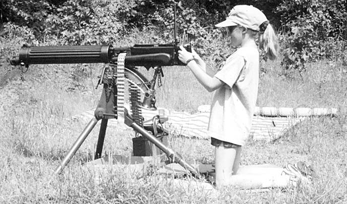
The finished project was a complete success. The new pins are a tight slip fit. The handles need to be wiggled a bit when inserting and removing the pins. That is just fine with me. Of course the real proof is in the results at the range. The barrel used has only 200 rounds through it. At about 100 yards I fired single shots for group. This produced the three inch pattern shown. Three shots were touching. If I applied a little downward pressure on the handles, I took up the small bit of slack in the elevating gear and its mountings. This is when the three touching holes were made. A ten shot burst produced the 6 inch group shown. A broader operating test was conducted by my friend John’s 12-year-old niece Santina. She gleefully dispatched a row of water-filled 2ltr. soda bottles at the base of the backstop with a series of short bursts.
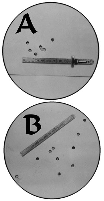
Some final thoughts. I increased the accuracy of my Vickers ten-fold by fitting new mounting pins in trued holes. There is still a bit of play in the pins that secure the elevating gear tumbler to its end of the crosshead. There is also a bit of play in the threads of the elevating gear. I may work on the attachment of the elevating gear to the crosshead sometime in the future It is not really necessary now. Remember, these guns were not designed or intended to, produce bench rest groups. Dolf Goldsmith’s excellent book, The Grand Old Lady of NoMan’s Land , mentions that the British Army accuracy standard was that 10 deliberately aimed shots fired at 400 yards should all be within a 24 inch square.
| This article first appeared in Small Arms Review V3N2 (November 1999) |


