By Dr. Ed Weitzman
Errol Back-Cunningham Served in the 1st South African Infantry (1SAI) in ’73 and latterly Cape Town Highlanders (CTH) between ’74 – ’83. Did my first service at Oudtshoorn Infantry. Base home of the infantry school in ’73 where the Vickers MG’s in the process of being re-chambered for .308 (7.62 NATO).
Some of the old .303 barrels in use at Oudtshoorn were so worn by then that we were experiencing trouble at 100 yds.
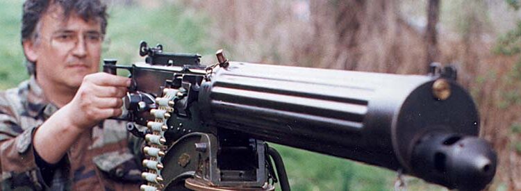
I was enamored with this beautiful piece of deadly machinery the first time I laid my eyes on one. That was in the epic movie, Lawrence of Arabia. The Arab army, under the command of TE Lawrence, had blown up a Turkish troop train. With two Vickers guns, they opened fire on the surviving Turks. The Vickers guns blazed away, belts dancing into the feed blocks, cocking levers flying back and forth; grim faced gunners emptying belt after belt into the hapless foe. I must have watched that scene a dozen times. Struck by the awesome combination of form and function in the Vickers gun, I was thoroughly hooked. When Dan asked me to start a series on the Vickers gun, I thought of the mountains of information available, and decided the best way to contribute was to start with the basics. This article deals with the disassembly, reassembly, and loading of the Vickers MKI machine gun.
The final design of the Mark l Vickers gun was the result of the needs of the British Commonwealth’s armed forces for a lighter, less expensive weapon to replace the heavy Maxim gun, which was adopted several years earlier. The new MKI Vickers gun was a result of a major redesign to lighten and refine the older Maxim gun. For this reason the Vickers Company initially referred to the gun as the “Light Maxim”. With its adoption by the army it was designated the MKI.
VICKERS DISASSEMBLY
The first step in disassembly of the gun is the same as with all guns; make sure it is not loaded. Due to its feed mechanism, the Vickers is somewhat more complex in this endeavor than most firearms. A live round can be in the chamber, or in the feed block in the extraction position at the top of its vertical travel, or in the feedway awaiting transport by the feed slide to the extraction position. Rotating the crank handle three times will ascertain that there are no cartridges in any of these three positions and ensure an empty gun.
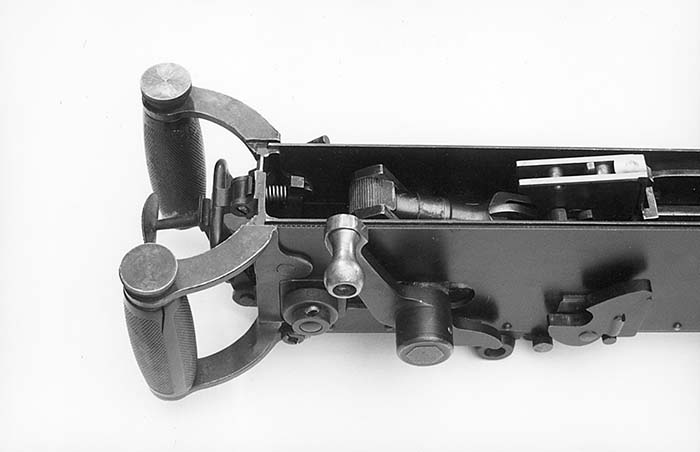
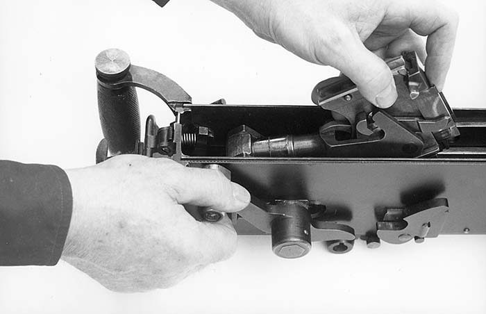
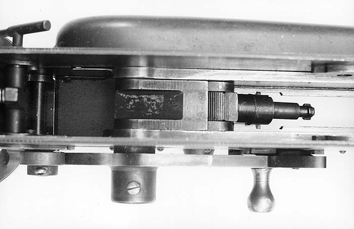
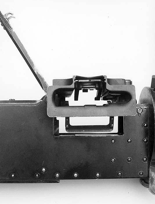

The “Lock” is the part that one might term a “Bolt” in other firearms. To remove the lock we must open the rear top cover, grasp the lock with the left hand then rotate the crank handle up and all the way to the rear,(fig1) while pulling upward on the front portion of the lock.(fig2) Then slowly lower the crank handle. When the lock has exited the gun it can then be rotated and removed from the connecting rod. (fig3) This may sound elementary, but make sure there is not a loaded cartridge in the lock before placing the lock aside. The firing pin is capable of striking the primer by accident, creating a sort of airburst from the cartridge. This would cause a negative experience. Close the top cover, open the feed block cover and pull upward on the feed block removing it from the gun. (fig4)
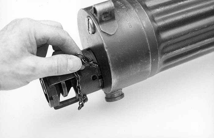
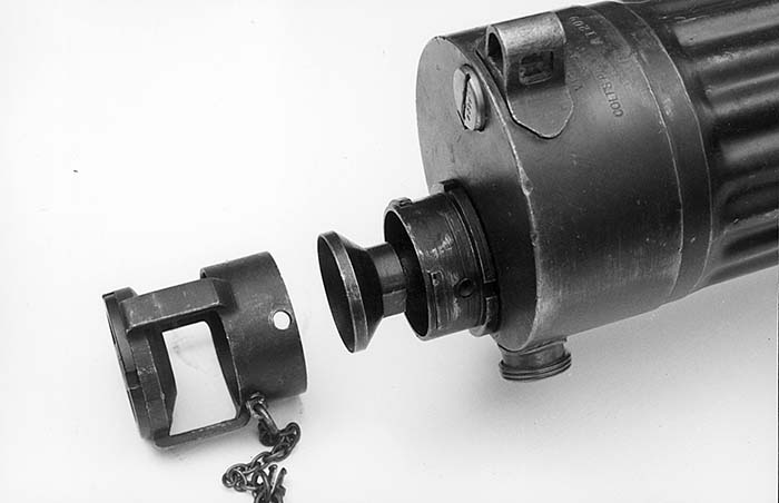
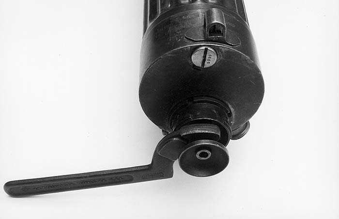
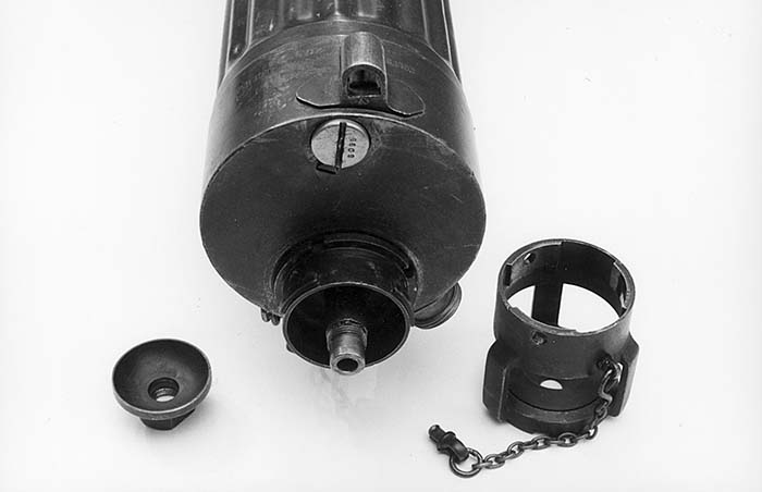
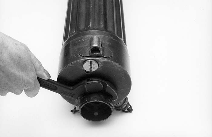
Moving to the muzzle end of the gun; remove the split pin holding the outer casing onto the muzzle gland.(fig5) Twist the casing 1/6th turn and pull it off of the gland.(fig6) If the outer casing is struck use a 1 1/4” to 3” adjustable spanner hook wrench in the notches of the front cone to facilitate removal. The same spanner wrench can next be use to remove the muzzle cup.(fig7) If the cup hasn’t been removed for some time it may be frozen to the barrel threads. The judicious use of an overnight penetrating oil soak and the light application of heat from a propane torch will facilitate the removal of the cup(fig8). The muzzle gland is removed next by unscrewing it with the spanner wrench.(fig9)
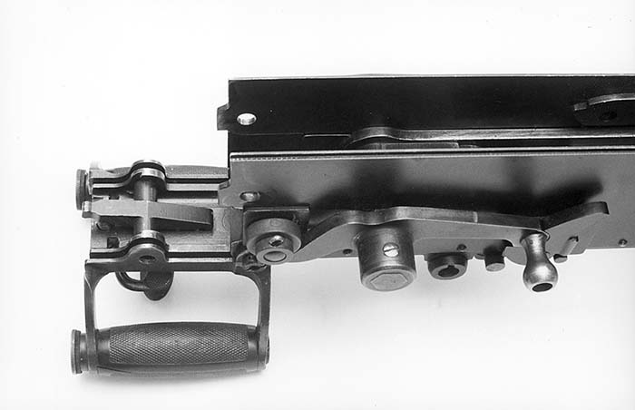
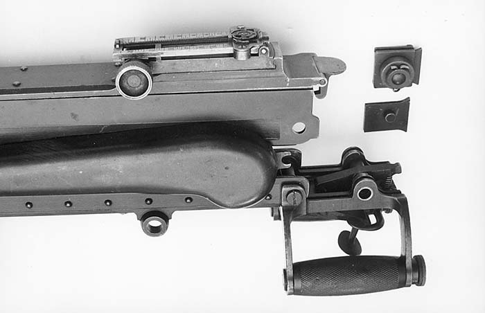


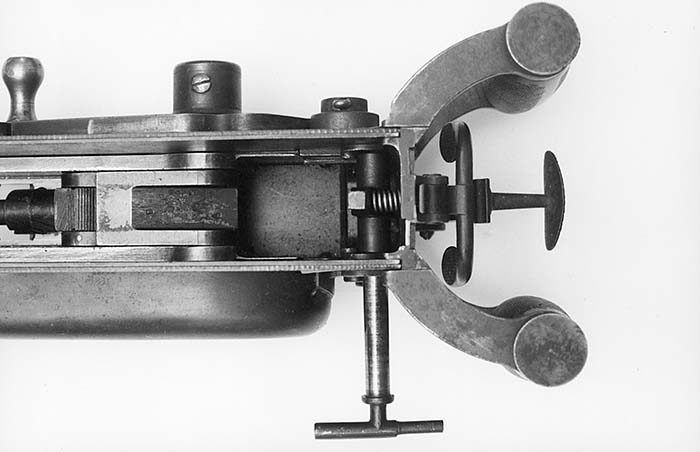
We next move to the rear handle and backplate assembly. This assembly is removed by unscrewing the “T” shaped upper fixing pin(fig10) and rotating the grips to the rear and down.(fig11) The right and left slides are then removed from the gun.(fig12) Push the fuzee cover forward, disengaging it from the front fixing pins, then unhook the fuzee chain assembly from the spring and place the fuzee assembly aside.(fig13) Rotate the fuzee chain assembly 1/8 turn clockwise and remove it from the crank.(fig14) By pulling the crank handle and connecting rod to the rear, the barrel, connecting rod and recoil plates are removed as an assembly from the rear of the receiver.(fig15) The recoil plates are then separated from the barrel trunions, freeing the barrel from the plates.(fig16) The steam tube is removed by removing the lock screw and unscrewing the steam tube with a large screwdriver. This is usually not necessary and not recommended for routine maintenance and cleaning. The rear cover and feedblock cover are secured by a common screw.
FEEDBLOCK & LOCK


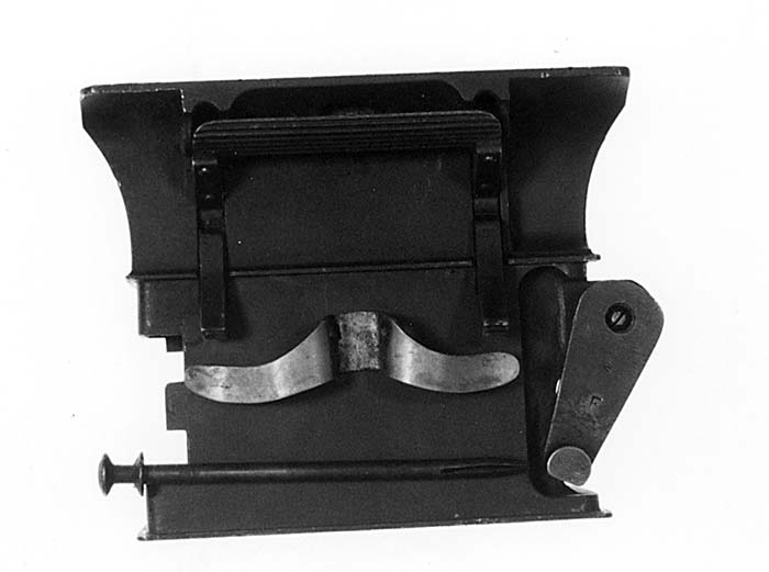


Disassembly of the feedblock is accomplished by using the “T” pin to push out the lever pin (fig17)and then, using a brass drift pin and suitable supports, drive off the lower feed lever. The upper feed lever is then removed and the feed slide drawn out of its slot.(fig18) Removal the of cross pin(fig19) frees the lower belt holding pawl and spring from the feedblock.(fig20) Disassembly of the grip plate is simply a matter of unscrewing the lower securing pin to remove it from the gun and then unscrewing the trigger lever axis pin and the safety catch axis pin,(fig21) all the parts will then unceremoniously fall into your lap. Paying attention to how the parts go together provides wonderful dividends when reassembling any mechanical device. To reassemble the feedblock, replace the slide, lower pawl, pawl spring and fixing pin into the positions they normally occupy. The top and bottom feed levers are then replaced making sure the stud on the top lever engages the hole in the feed slide and locks in place with the split pin.


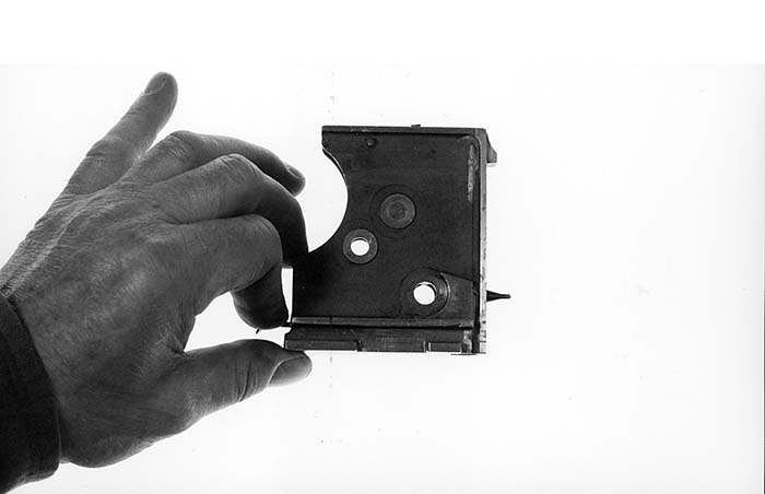

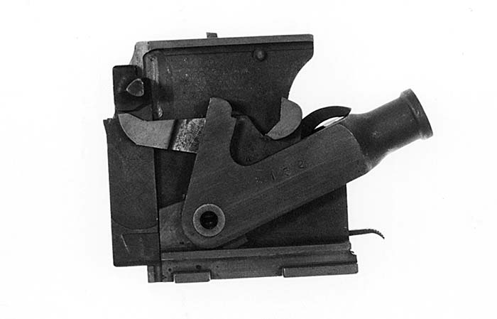
Disassembly and assembly of the lock was best described by George Ironside of Vickers Ltd., in a manual he wrote in 1917 for Colts Patent Firearms Mfg. Co. This was to be issued to the US Troops with their Vickers gun. He instructs as follows: “Remove the lock from gun. (If already out of gun see that it is cocked). (fig22)Press out the side levers pin and bushing and remove side levers (Use the “T” pin from handle block (fig23)or the special steel drift). Detach lifting levers. Slide off carrier. (fig24)Depress safety sear and fire the lock by pulling on handsear. (Note: – Keep hand clear of firing pin hole). Press out tumbler pin and remove tumbler.(fig25) Press out hand sear axis pin and remove hand sear and mainspring. Depress safety sear and allow firing pin to drop out.(fig26) Unhook safety sear and remove it with its spring, but do not spring from the safety sear.(fig27) Note: The safety sear axis pin is not a removable part being riveted to the lock frame. Push out gib spring plate and remove gib spring and gib from carrier. To assemble the lock; Replace gib, gib spring and gib spring plate in carrier. From this stage have flat in left hand, keyway side uppermost. Insert safety sear with spring. Insert firing pin. Place tumbler and insert pin. Place hand sear and insert pin. Slide on carrier (firing pin being in cocked position). Put on side levers and secure with bushing and side levers pin. With firing pin forward in fired position, insert mainspring, pushing it into place. Full cock the lock.”(fig28)
FINAL REASSEMBLY
The grip assembly is reassembled by replacing the safety catch, trigger and trigger bar lever in their respective recesses and replacing their retaining screws. The grip assembly is attached to the gun with the lower grip retaining screw and nut and then placed in the open (horizontal) position. The balance of the gun is reassembled by first placing the recoil plates and crank assembly on the barrel trunions, and ensuring that the packing is in place. Then insert the assembly barrel first into the rear of the receiver. Guide the barrel forward into the water jacket until the muzzle protrudes from the front of the water jacket. As the crank handle enters the rear slots of the receiver, care must be taken to see that the muzzle packing is not dislodged by the barrel as it enters the front packing gland. With the barrel and recoil plates in place the fuzee spring chain is inserted in the recess in the crank and given a 1/8 th turn counter-clockwise to engage the locking tabs. The fuzee spring hook is then engaged in the fuzee chain and the fuzee cover pushed forward hooking the front notches under the front fixing studs. The two slides are placed in the receiver making sure the slide with the roller goes in the right side and the slide with the fuzee stud goes in the left. The grip plate is then rotated upwards and locked in the closed position by replacing the T fixing pin.
Replace the feed block in the receiver, making sure the feed lever crank is engaged in the slot in the recoil plate extension by pushing the feed slide all the way into the feed block while lowering the block in place.
Replace the muzzle gland and tighten with the spanner wrench, followed by installing the muzzle cup. A small amount of anti-seize compound applied to the barrel threads will make future removal easier. Tighten the cup snugly with the spanner wrench. A moderate rap to the spanner wrench with a rawhide mallet will prevent loosening of the cup during firing. The outer booster casing is engaged in the attaching lugs of the muzzle gland and turned clockwise. It will stop with the fixing holes lined up wherein you place the split pin.
If you removed the front and rear covers, they are replaced by securing with their common screw and nut. Open the rear cover and replace the lock by engaging it on the crank pin, turning it to line up with the rails on the barrel extensions, then lower it into the receiver. Cycling the crank once will engage the lock in its guide recess and return it to its forward position. Closing the rear cover completes your reassembly.
LOADING
Now for the fun part. Along with the gun, tripod and ammunition, I would recommend you also take along coolant, a funnel, some hi temp grease, and oil. Other items in your “Kit” should include a steel cleaning rod, broken cartridge extractor, screwdriver, pliers, a wooden mallet, hook spanner wrench, one welders glove, packing cord, and a spare lock if you have one. You will find that if you take a spare lock along, nothing will break. If, however, you don’t have one, something inevitably will break. Mr. Murphy may well have had a hand in designing the Vickers.
Set up the tripod, making sure the leg position locking levers are tight. You should give each one a rap with the mallet after hand tightening. Secure the gun in the tripod with the front and rear trunion pins. For a coolant, I have found a 10-1 mixture of water and soluble oil to be ideal. The soluble oil is sold by industrial supply houses and is used as a lubricant and coolant for machining operations. After the coolant is drained from the gun, the water evaporates leaving a protective oil coating inside the water jacket. This stuff is sold by the gallon and is relatively inexpensive. I save and reuse mine, so a gallon will probably last either five years, one World War, or 50 strafing attacks on Turkish troop trains. Using your funnel (you did remember to bring one, didn’t you?) fill the water jacket about 3/4 full with the coolant mixture and replace the brass filler plug.
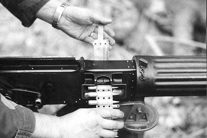
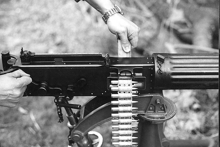
Place the belt box on the ground below the feed block on the right side. Withdraw the belt from the box and insert the metal tab into the feed block, grasping the tab as it protrudes through on the right side. While maintaining tension on the belt with the left hand, rotate the cocking lever all the way to the rear and release it. This allows the first round to advance into the extraction position in the feed block and as the lock closes the extractor rises to grasp the rim of the cartridge. Still maintaining tension on the belt, rotate and release the cocking lever a second time. This withdraws the round from the belt, cams the extractor down and with the forward stroke chambers the round and returns the extractor up to grasp the rim of the next round. The Vickers is now loaded and ready to fire.
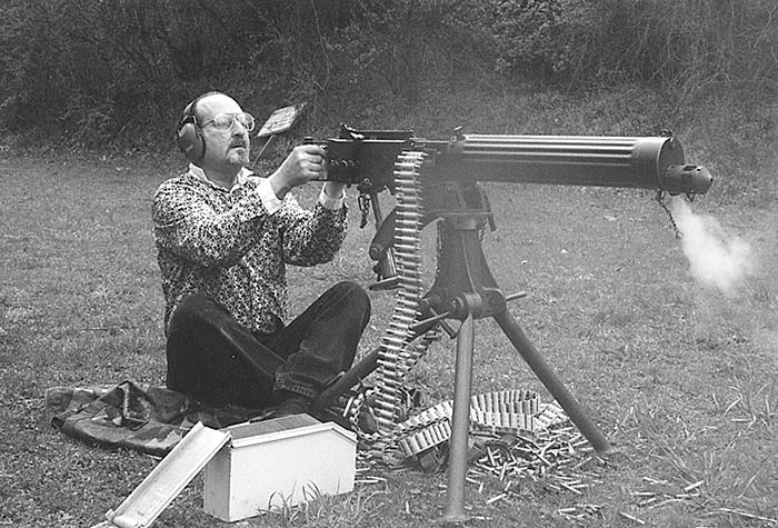
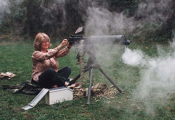
Grasp the grips with both hands and while lifting the safety bar with the index fingers, press the trigger with the thumb. The first round will fire, and the whole loading/ firing process is repeated automatically until the belt is empty or the trigger is released. Let loose an audible sigh of satisfaction, and insert another belt.
If a partially empty belt is to be removed from the gun, you must grasp the upper and lower belt pawls and, while pressing in on the pawls, withdraw the belt from the right side of the feed block. Then by rotating the cocking lever twice you will insure that there are no remaining cartridges in the gun. As an additional safety precaution, before placing anyone in front of the gun, open the rear cover and withdraw the lock. Give the lock a 1/4 turn clockwise and then place it on the receiver rails, thereby “hanging the lock”.
In future issues of SAR, Dr. Weitzman will be presenting articles on the various models of the Vickers guns, as well as tips for shooting and maintaining these fine weapons. If you have Vickers questions, send them to Dr. Weitzman C/O SAR, and we will try to wheedle, bribe, or pistol whip him into answering you.
| This article first appeared in Small Arms Review V1N10 (July 1998) |


