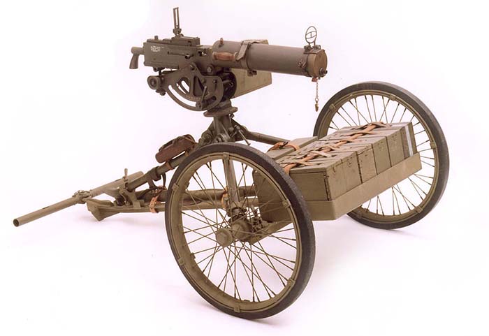
Fully mounted M1 cart with draw bar attached to lunette. Note the five ammunition boxes and one spare parts box (denoted by white stripe) mounted to the front of the axle.
Robert G. Segel
The Mount, Wheeled, Machine Gun, M1 was the logical design progression of the larger and heavier World War I era wood and steel M1917 Machine Gun Cart. The M1917 Machine Gun Cart was used strictly as a means of transportation for one of several types of machine guns (Colt Vickers M1915, Lewis Gun M1917, and the Colt Automatic Gun M1914) and included the gun, mount, ammunition boxes, belt loader box, water chest, spare parts box, various accessories, range finder, tools, mule skinner equipment, pioneer tools, etc. Though it could be man drawn, its design, size and weight dictated that it be mule drawn for optimal usage.
Adopted in 1927, the M1 Machine Gun Cart was designed specifically to provide means by which a Browning M1917A1 water-cooled machine gun, mounted on the M1917 tripod mount, may be transported by man or animal draft without separating the gun from its tripod or otherwise disassemble elements which require time to prepare the gun for action. This manifested itself by combining the idea of a T base for the M1917 tripod with that of a light weight, maneuverable 2-wheeled cart that could carry the gun in the ready to fire position along with ammunition and selected accessories.
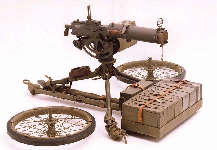
The T base (trail assembly) is designed and constructed to accommodate the M1917 tripod in a fixed position by clamping the forward tripod legs at each end of a 2×2-inch commercial grade steel tee, 38 inches long, and the rear leg to a wider tee welded at right angles to the first. When the wheels are removed, the T base with the gun and tripod attached may be set directly on the ground. The trailing leg of the T has a reinforcing spade at the rear that transfers the recoil stress to the ground. The advantage of laying the T base with tripod and gun secured in place is particularly valuable in sand and soft ground by distributing the weight of the entire unit over a wide flat surface area. Otherwise, placing just the tripod and gun in this type of soft earth environment, the tripod feet would bury into the soft ground or sand and the gun would become unstable. Conversely, on solid ground, the wheels can remain in place and the gun brought into action expeditiously in situ.
There are two clamping devices bolted to each end of the cross tee (axle). One set to hold the left and right tripod legs and one set to hold each wheel. The front tripod leg brackets have a plain, cylindrical bearing with a swinging clamp and are secured by a securing bolt with a clamping handle. A similar clamp is located on the trail assembly to hold the rear tripod leg. The wheel clamps are also arranged for quick engagement or disengagement with stub axle spindles mounted in ball bearings in the hubs of the rubber-tired wheels. With the spindle clamped in place, the wheels are parallel and approximately 42 inches apart, center to center. Release of the tripod leg clamps or axle spindle is achieved by simply unscrewing the clamping handle, backing it off against the stop washer on the bolt, and swinging the bolt and clamp clear. It should be noted that when removing the wheels, it is definitely not a one man operation. Opening the spindle clamp will allow the heavily loaded cart to drop unless supported by at least two members of the machine gun crew. The position is awkward and it is well advised to keep one’s feet from under.
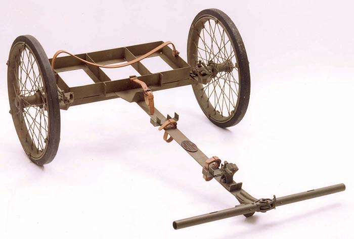
The wheels are a wire-spoke motor cycle type with a solid rubber tire 25 inches outer diameter that is wired onto the ordinary clincher rim used for pneumatic tires. The wheel has 20 spokes outside 10¼ inches long, and 20 spokes inside 10 inches long.
On the rear end of the trail is a flat ring lunette with a 1½ inch hole. The drawbar, which is 35½ inches long, may be slipped over the lunette and secured by the retaining pin through the lunette hole when it is desired to draw or push the mount by man power.
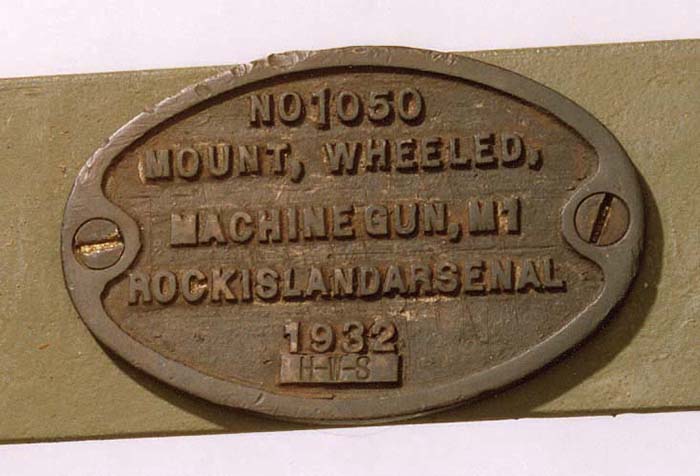
Welded to the top of the cross bar above the axle is a rack with a leather strap for carrying six ammunition boxes. The rack is designed to accommodate the early wood ammunition boxes. A separate rack with a leather strap to hold the metal M1 water chest is located directly behind the ammunition rack. The water chest lies horizontally and it is necessary to change the position of the water chest before the steam condensing device can be used. A belt filling box and/or a spare parts box may be substituted for an ammunition box. The drawbar, cleaning rod and a canvas cover containing a spare barrel are carried in brackets and secured by two leather straps on the trail. The data plate is located in the center top of the trail.
The spread of the tripod legs is fixed on the T base. Thus, the limits of elevation of the gun are those of the tripod head. This is variable, however, depending on whether the wheels are assembled to or detached from the T base.
The M1 Machine Gun Cart had a unit cost of $95.76. It was used throughout world in the 1930s by the Army and Marines but was declared obsolete by the time the United States entered World War II and saw active combat service only with those units that still had them at the outbreak of the war. The M1 Machine Gun Cart was replaced with the M3A4/M4A1 Machine Gun Cart during World War II. The M1 Machine Gun Cart is an exceptionally rare accessory for the Browning M1917A1 machine gun. Other than a handful in museums, this author is aware of only four in private collections.
| This article first appeared in Small Arms Review V7N11 (August 2004) |


