Small Arms Review
  • Home
  • Articles
    • Guns & Parts
    • Suppressors
    • Optics & Thermals
    • Ammunition
    • Gear
    • News & Opinion
    • Columns
    • Museums & Factory Tours
    • ID Guides
    • Interviews
    • Event Coverage
    • Articles by Issue
      • Volume 1
        • V1N1 (Oct 1997)
        • V1N2 (Nov 1997)
        • V1N3 (Dec 1997)
        • V1N4 (Jan 1998)
        • V1N5 (Feb 1998)
        • V1N6 (Mar 1998)
        • V1N7 (Apr 1998)
        • V1N8 (May 1998)
        • V1N9 (Jun 1998)
        • V1N10 (Jul 1998)
        • V1N11 (Aug 1998)
        • V1N12 (Sep 1998)
      • Volume 2
        • V2N1 (Oct 1998)
        • V2N2 (Nov 1998)
        • V2N3 (Dec 1998)
        • V2N4 (Jan 1999)
        • V2N5 (Feb 1999)
        • V2N6 (Mar 1999)
        • V2N7 (Apr 1999)
        • V2N8 (May 1999)
        • V2N9 (Jun 1999)
        • V2N10 (Jul 1999)
        • V2N11 (Aug 1999)
        • V2N12 (Sep 1999)
      • Volume 3
        • V3N1 (Oct 1999)
        • V3N2 (Nov 1999)
        • V3N3 (Dec 1999)
        • V3N4 (Jan 2000)
        • V3N5 (Feb 2000)
        • V3N6 (Mar 2000)
        • V3N7 (Apr 2000)
        • V3N8 (May 2000)
        • V3N9 (Jun 2000)
        • V3N10 (Jul 2000)
        • V3N11 (Aug 2000)
        • V3N12 (Sep 2000)
      • Volume 4
        • V4N1 (Oct 2000)
        • V4N2 (Nov 2000)
        • V4N3 (Dec 2000)
        • V4N4 (Jan 2001)
        • V4N5 (Feb 2001)
        • V4N6 (Mar 2001)
        • V4N7 (Apr 2001)
        • V4N8 (May 2001)
        • V4N9 (Jun 2001)
        • V4N10 (Jul 2001)
        • V4N11 (Aug 2001)
        • V4N12 (Sep 2001)
      • Volume 5
        • V5N1 (Oct 2001)
        • V5N2 (Nov 2001)
        • V5N3 (Dec 2001)
        • V5N4 (Jan 2002)
        • V5N5 (Feb 2002)
        • V5N6 (Mar 2002)
        • V5N7 (Apr 2002)
        • V5N8 (May 2002)
        • V5N9 (Jun 2002)
        • V5N10 (Jul 2002)
        • V5N11 (Aug 2002)
        • V5N12 (Sep 2002)
      • Volume 6
        • V6N1 (Oct 2002)
        • V6N2 (Nov 2002)
        • V6N3 (Dec 2002)
        • V6N4 (Jan 2003)
        • V6N5 (Feb 2003)
        • V6N6 (Mar 2003)
        • V6N7 (Apr 2003)
        • V6N8 (May 2003)
        • V6N9 (Jun 2003)
        • V6N10 (Jul 2003)
        • V6N11 (Aug 2003)
        • V6N12 (Sep 2003)
      • Volume 7
        • V7N1 (Oct 2003)
        • V7N2 (Nov 2003)
        • V7N3 (Dec 2003)
        • V7N4 (Jan 2004)
        • V7N5 (Feb 2004)
        • V7N6 (Mar 2004)
        • V7N7 (Apr 2004)
        • V7N8 (May 2004)
        • V7N9 (Jun 2004)
        • V7N10 (Jul 2004)
        • V7N11 (Aug 2004)
        • V7N12 (Sep 2004)
      • Volume 8
        • V8N1 (Oct 2004)
        • V8N2 (Nov 2004)
        • V8N3 (Dec 2004)
        • V8N4 (Jan 2005)
        • V8N5 (Feb 2005)
        • V8N6 (Mar 2005)
        • V8N7 (Apr 2005)
        • V8N8 (May 2005)
        • V8N9 (Jun 2005)
        • V8N10 (Jul 2005)
        • V8N11 (Aug 2005)
        • V8N12 (Sep 2005)
      • Volume 9
        • V9N1 (Oct 2005)
        • V9N2 (Nov 2005)
        • V9N3 (Dec 2005)
        • V9N4 (Jan 2006)
        • V9N5 (Feb 2006)
        • V9N6 (Mar 2006)
        • V9N7 (Apr 2006)
        • V9N8 (May 2006)
        • V9N9 (Jun 2006)
        • V9N10 (Jul 2006)
        • V9N11 (Aug 2006)
        • V9N12 (Sep 2006)
      • Volume 10
        • V10N1 (Oct 2006)
        • V10N2 (Nov 2006)
        • V10N3 (Dec 2006)
        • V10N4 (Jan 2007)
        • V10N5 (Feb 2007)
        • V10N6 (Mar 2007)
        • V10N7 (Apr 2007)
        • V10N8 (May 2007)
        • V10N9 (Jun 2007)
        • V10N10 (Jul 2007)
        • V10N11 (Aug 2007)
        • V10N12 (Sep 2007)
      • Volume 11
        • V11N1 (Oct 2007)
        • V11N2 (Nov 2007)
        • V11N3 (Dec 2007)
        • V11N4 (Jan 2008)
        • V11N5 (Feb 2008)
        • V11N6 (Mar 2008)
        • V11N7 (Apr 2008)
        • V11N8 (May 2008)
        • V11N9 (Jun 2008)
        • V11N10 (Jul 2008)
        • V11N11 (Aug 2008)
        • V11N12 (Sep 2008)
      • Volume 12
        • V12N1 (Oct 2008)
        • V12N2 (Nov 2008)
        • V12N3 (Dec 2008)
        • V12N4 (Jan 2009)
        • V12N5 (Feb 2009)
        • V12N6 (Mar 2009)
        • V12N7 (Apr 2009)
        • V12N8 (May 2009)
        • V12N9 (Jun 2009)
        • V12N10 (Jul 2009)
        • V12N11 (Aug 2009)
        • V12N12 (Sep 2009)
      • Volume 13
        • V13N1 (Oct 2009)
        • V13N2 (Nov 2009)
        • V13N3 (Dec 2009)
        • V13N4 (Jan 2010)
        • V13N5 (Feb 2010)
        • V13N6 (Mar 2010)
        • V13N7 (Apr 2010)
        • V13N8 (May 2010)
        • V13N9 (Jun 2010)
        • V13N10 (Jul 2010)
        • V13N11 (Aug 2010)
        • V13N12 (Sep 2010)
      • Volume 14
        • V14N1 (Oct 2010)
        • V14N2 (Nov 2010)
        • V14N3 (Dec 2010)
          • Ammunition
        • V14N4 (Jan 2011)
        • V14N5 (Feb 2011)
        • V14N6 (Mar 2011)
        • V14N7 (Apr 2011)
        • V14N8 (May 2011)
        • V14N9 (Jun 2011)
        • V14N10 (Jul 2011)
        • V14N11 (Aug 2011)
        • V14N12 (Sep 2011)
      • Volume 15
        • V15N1 (Oct 2011)
        • V15N2 (Nov 2011)
        • V15N4 (Jan 2012)
        • V15N5 (Feb 2012)
      • Volume 16
        • V16N1 (1st Quarter 2012)
        • V16N2 (2nd Quarter 2012)
        • V16N3 (3rd Quarter 2012)
        • V16N4 (4th Quarter 2012)
      • Volume 17
        • V17N1 (1st Quarter 2013)
        • V17N2 (2nd Quarter 2013)
        • V17N3 (3rd Quarter 2013)
        • V17N4 (4th Quarter 2013)
      • Volume 18
        • V18N1 (Jan Feb 2014)
        • V18N2 (Mar Apr 2014)
        • V18N3 (May Jun 2014)
        • V18N4 (Jul Aug 2014)
        • V18N5 (Sep Oct 2014)
        • V18N6 (Nov Dec 2014)
      • Volume 19
        • V19N1 (Jan 2015)
        • V19N2 (Feb Mar 2015)
        • V19N3 (Apr 2015)
        • V19N4 (May 2015)
        • V19N5 (Jun 2015)
        • V19N6 (Jul 2015)
        • V19N7 (Aug Sep 2015)
        • V19N8 (Oct 2015)
        • V19N9 (Nov 2015)
        • V19N10 (Dec 2015)
      • Volume 20
        • V20N1 (Jan 2016)
        • V20N2 (Feb Mar 2016)
        • V20N3 (Apr 2016)
        • V20N4 (May 2016)
        • V20N5 (Jun 2016)
        • V20N6 (Jul 2016)
        • V20N7 (Aug Sep 2016)
        • V20N8 (Oct 2016)
        • V20N9 (Nov 2016)
        • V20N10 (Dec 2016)
      • Volume 21
        • V21N1 (Jan 2017)
        • V21N2 (Feb Mar 2017)
        • V21N3 (Apr 2017)
        • V21N4 (May 2017)
        • V21N5 (Jun 2017)
        • V21N6 (Jul 2017)
        • V21N7 (Aug Sep 2017)
        • V21N8 (Oct 2017)
        • V21N9 (Nov 2017)
        • V21N10 (Dec 2017)
      • Volume 22
        • V22N1 (Jan 2018)
        • V22N2 (Feb 2018)
        • V22N3 (March 2018)
        • V22N4 (Apr 2018)
        • V22N5 (May 2018)
        • V22N6 (Jun Jul 2018)
        • V22N7 (Aug Sep 2018)
        • V22N8 (Oct 2018)
        • V22N9 (Nov 2018)
        • V22N10 (Dec 2018)
      • Volume 23
        • V23N1 (Jan 2019)
        • V23N2 (Feb 2019)
        • V23N3 (Mar 2019)
        • V23N4 (Apr 2019)
        • V23N5 (May 2019)
        • V23N6 (Jun Jul 2019)
        • V23N7 (Aug Sep 2019)
        • V23N8 (Oct 2019)
        • V23N9 (Nov 2019)
        • V23N10 (Dec 2019)
      • Volume 24
        • V24N1 (Jan 2020)
        • V24N2 (Feb 2020)
        • V24N3 (Mar 2020)
        • V24N4 (Apr 2020)
        • V24N5 (May 2020)
        • V24N6 (Jun Jul 2020)
        • V24N7 (Aug Sep 2020)
        • V24N8 (Oct 2020)
        • V24N9 (Nov 2020)
        • V24N10 (Dec 2020)
  • The Archive
    • Search The Archive
  • Store
    • Books
    • Back Issues
    • Merchandise
  • Podcast
  • Newsletter
  • Events
  • FrankenGun Challenge
  • About
    • About Small Arms Review
    • About Chipotle Publishing
    • Contact Us
    • Other Publications
      • Small Arms Defense Journal
No Result
View All Result
Small Arms Review
No Result
View All Result
Home Articles

RAFFICA SPECIAL- THE RPG-7 SYSTEM

SAR Staff by SAR Staff
August 2, 2022
in Articles, V10N3 (Dec 2006)
RAFFICA SPECIAL- THE RPG-7 SYSTEM
Share on FacebookShare on Twitter

interview by Dan Shea

Dear readers of Raffica: On occasion a subject question becomes too large for our normal Q&A format. When that occurs, we move to a “Raffica Special” and we are in that position right now. We have had so many questions regarding the operation of the RPG-7 system that the only way to properly answer this is with a “Special.” Since I have been working on a photo ID series of the various basic RPG systems for many years, and we were just preparing to do the ultimate worldwide ID Guide to these launchers, we decided to prep the readers with this How It Works guide first. Several other articles will soon follow including the RPG ID Guide and an in-depth analysis of the sighting systems. We hope this guide helps dispel many of the myths surrounding the RPG-7 system, and educates our readers to the basic functions and differences. – Dan

Soviet RPG-2 launcher with strap, covers and grenade in firing position. This specimen dates from 1952.

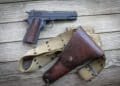
Shoulder fired rocket launchers are nothing new. Neither are rifles with integral grenade launchers for that matter. In the 18th century, there were seven foot long flintlock style rifles that a rocket shaft was aligned in, and a transfer bar operated the flintlock mechanism located out at the front of the launcher. The buttstock, trigger group, etc., look normal, then the lock was out at the very front. There was another design from the same period where the buttstock was cylindrical and opened up at the shoulder end to make a cup style grenade launcher. The lock was able to fire either the musket barrel or the grenade launcher with the flick of a switch. The grenade launcher was used mortar style of course. These are mentioned simply to show that weapons designers have been making man portable launchers and hurlers for centuries. It is only in the modern times that we have fine tuned the process.

People’s Republic of China Type 56 variant of the RPG-2. This is the 40mm straight tube launcher primarily used by the Viet Cong forces early on during the Vietnam War. It was referred to as the B40, and some B40s were made in North Vietnam. Later in the war- approximately 1967- the RPG-7 was used. This specimen dates from 1956.

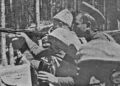
The roots of the RPG-7 launcher can be found in the German Panzerfaust (literally “Tank-Fist” in German) of World War II. This was little more than a tube with a firing mechanism to launch a primitive warhead, but it gave the infantryman the ability to launch an explosive charge farther than he had been able to previously. Developments during and after World War II went in several directions, with some countries concentrating on the recoilless rifle principle and others looking more to shoulder fired rocket launchers.

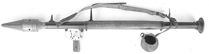
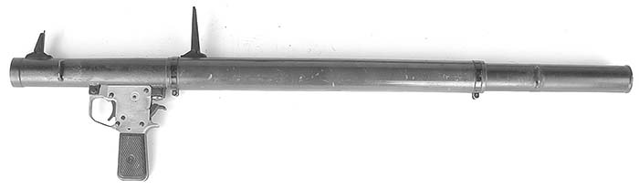
In 1948-49, the Soviets introduced the RPG-2 system. The RPG-2 initially was a simple tube with a rocket propelled grenade that was fired from it. Behind the rocket was an expeller charge that basically threw the rocket forward from the tube, and then a pyrotechnic fuze fired the rocket itself when it was safely in front of the operator. The RPG-2 rockets were not reliably timed for firing so the accuracy degraded at distances beyond 100 meters. Stabilization came from six thin sheet metal fins at the rear of the rocket motor, which did a reasonable job for accuracy. The RPG-2 series had an expected range of 150 meters, so the sights were fixed ladder types with no allowance for adjustment. Later models had some modifications, such as a rudimentary blast shield at the rear to help keep any backblast away from the operator. This was neither a blast cone nor a venturi.

Rudimentary blast deflector on the rear of this RPG-2 was designed as an afterthought to prevent any of the backblast coming forward onto the operator.
The RPG-2 round has a raised metal projection that indexes into a channel on the top of the RPG-2 launcher directly in front of the flip up front sight. Part of the assistant gunner’s job was to ensure that the round was positively in position when he loaded it. If it wasn’t indexed and seated, then the primer would not be in the proper position for the firing pin, resulting in a “No-fire” situation. Of all problems on the RPG series, lack of proper alignment is the cause of most failures to fire in the field.

The RPG-2 system was manufactured until its replacement, the RPG-7, appeared in 1962. The Communist Chinese built and distributed the B-40, an RPG-2 variant, and the Yugoslav’s built a much heavier similar launcher called the M57.

Dummy RPG-2 round with fins extended, and one type of dummy ejection charge underneath it. The ejection charge would be removed from packaging directly before firing and screwed onto the back of the round. The charges are very moisture and physical damage sensitive, but less so than RPG-7 charges.

It is strongly recommended against firing RPG-2, M57, or B-40 rounds as there has not been recent manufacture and the chemical compositions and fuzes are now untrustworthy. Unless the operator can verify recent manufacture, these should be avoided. The launchers themselves are simple mechanical devices so with fresh ammunition they would be fieldable. Antique, outdated and outclassed, but fieldable RPG-2 series grenades do not have timed safety self destruct fuzes, so a “dud” round will become a UXO (Un-Exploded Ordnance) hazard.

RPG-2 fins extended. At the front of the fins, towards the nose cone, there are some spring steel wire rings. These are normally over the fins, holding them to the body of the rocket section. When the ejection charge is screwed on, then the grenade is inserted into the RPG-2 tube, these rings are pushed forward by the tube, and the six fins try to open. These fins exert outward pressure on the inside of the RPG-2 tube, and hold the grenade in place.
If the RPG-2 round is removed from the RPG-2, the fins will extend. In this photo, the ejection charge has been unscrewed, and the fins are being manually held in. This shows that the fins can be held down enough to reinsert the round into the RPG-2 launcher (Ejection charge would be on for this). However, once the fins have been extended, and the operator desires to put the round away for storage, it would require holding the fins down firmly enough to slide the retaining rings back over them. This can not generally be done by hand. There is a cup shaped metal tool with six slots in it that can be slid over the extended fins, then rotated with the fin direction, folding the fins down. Once wound completely on, the retaining rings can be slid in place and the round can be stored again. Return to storage or carrier also depends on if there is any type of fuze safety involved (Later Yugo style) that must be replaced before storage.

RPG-7

Close up view of one of the signature appearances of the RPG-7 series; the Blast cone at the rear. This is actually a divergent nozzle, which will accelerate supersonic gases.
RPG-7V, left hand view. This example is dated 1966. Note the much larger central tube section, the blast cone at the rear, and the addition of a second handgrip.
Right side view of a fully cutaway RPG-7V tube.

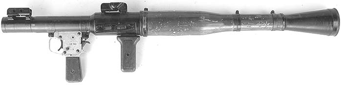
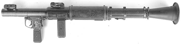
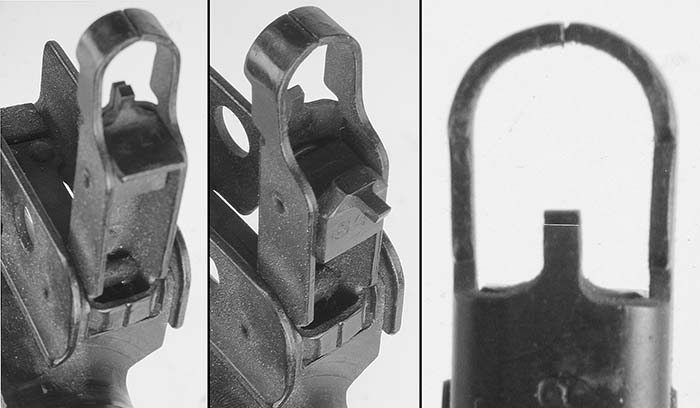
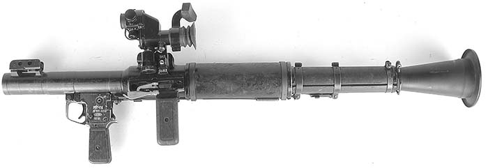
For the purposes of this article, we will be discussing the Russian/Soviet made RPG-7 series: the RPG-7V and RPG-7D. There are approximately 29 different variations made around the world and SAR will be covering models and countries of manufacture at a later date in the ID Guide. Two of the most basic designs have been copied by many countries: the Soviet style and the Chinese style. The fastest way to tell which school the RPG came from is that the Chinese style utilizes a bipod, a shoulder rest, and has adjustable front and rear sights, while the original Russian model does not.

RPG-7V trigger group with markings.
On the right is the standard diameter of the 40mm tube. The rocket section fits here, and the expeller charge fits to the center of the expansion tube in the middle. This is one of the major upgrades in the RPG- 7 system. The base of the expeller charge seats into the narrowed section to the left.
On the right of this closeup is the expansion chamber area. The expeller charge base slides in from the right and seats firmly into the narrowed section at the center. The foam plug at the base of the expeller charge actually seats there. This photo also shows the joint between the forward tube and the rear tube in manufacturing. Although this is threaded, this is not an armorer’s disassembly point as it is welded. Also, the narrowing at the joint is a venturi: a narrowing of the tube going to an increased diameter, which changes gas flow pressure direction and speed.

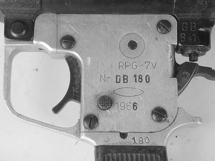
Several initial changes appear in the RPG-7 series. The example in these photos is the second variation, the RPG-7V. The “V” model is simply a bit smaller dimensionally, and lighter. The tube inner diameter remains at 40mm. Several manufacturing method improvements were instituted.
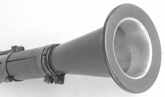
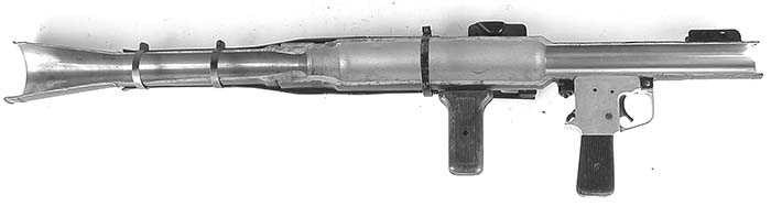
RPG-7D

Left side view of Soviet RPG-7D paratrooper take down version, manufactured in 1973.
Left side view of Soviet RPG-7D paratrooper take down version in the “carry” position.
RPG-7D locking latch that snaps into place when the tubes are properly mated together and ready to fire. If the tubes are not properly placed, the latch extension blocks the sear.
Male and female sides of the three lug interlocking section of the RPG-7D tube.
The RPG-7D safety latch extension is a rod that leads from the barrel connecting latch down to the sear area, and either blocks or allows the sear to operate.
The sear block is a sheet metal piece that fits around the firing pin well, and moves forward or backwards depending on the position of the locking latch.
The front and rear tubes are connected together with two bayonet lugs. Once locked into place, they are very securely attached. The hammer needs to be cocked and safety “On” in order for the rear tube to slide into place, or the trigger group needs to be removed.
The RPG-7D trigger group has a notch on the top right hand plate that fits around the sear block mechanism. Installation and removal of the RPG-7D trigger group requires more manipulation than a straight “on-off” like the standard groups. The operator needs to ensure the sear block mechanism is not compromised or bent when he installs the trigger group.
Standard Russian/Soviet style front sight. There are no adjustments. Chinese style front sights have drift and height adjustments. This is the only authorized position used for the front sight for firing an RPG-7.

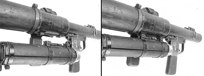
The RPG-7D is the paratrooper’s takedown version of the RPG-7 system, which appeared in the early 1970s. There is a three lug turning takedown point with various safety features built in to avoid firing without the rear of the tube properly attached. There are two bayonet lugs used to attach the rear section to the forward tube, making for a much smaller package for jumping with.
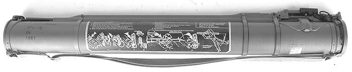
RPG-18
(Side block of four pics)

While the Warsaw Pact nations were pursuing the RPG series of shoulder fired rocket propelled grenade launchers that were reloadable, the US and her allies were concentrating on disposable single shot launchers; most notably the LAW M72 series of launchers. By the mid 1970s, the Soviets had experimented with their own disposable launcher, and it was called the RPG-18. There are numerous job specific RPGs of this style today; RPG-22, RPG-26, RPG-27, the Serbian M80. Essentially, the RPG-18 is like the LAW in most operational regards.
At the rear of an RPG-18, just like in the LAW M72, there is a plastic tube with fast burning explosive powder in it that takes the mechanically fired primer gases and transmits the ignition to the rear of the rocket tube to ignite the propellant.
There are two sizes of propellant strip in the rocket, that ignite in order.
Cutaway view of the shaped charge of the RPG-18, showing the similar design to the RPG-7; piezo nose fuze, rear firing fuze with explosive compound and tin coated copper cone for forming the jet.

Aiming and Boresighting

Rear sight on the Russian/Soviet style RPG-7 has only up and down movement. Chinese style has more adjustments.
The rear sight is locked into either the up or down position with a leaf spring in the base.

The objective is to hit the target, and more specifically, to strike a crippling blow to the target. If the target is a tank or self-propelled gun, the goal is to take the gun out of action. Simply taking a tread or other immobilizing shot is good but keep in mind that the operators of the vehicle will be looking to return fire, and even if they are immobilized, if they can bring the main gun to bear then the RPG team is in danger as it takes 8-12 seconds to load another round.

Far left – Normal temperature firing position for the front sight is with the auxiliary sight snapped upwards into the fire position. Center – For firing under 0 degrees centigrade, the auxiliary front sight is snapped to the down, inactive position. This lowers the front sight peak, effectively raising the point of aim which is necessary due to rocket trajectory at lower temperatures. Right – Front sight in normal use. The white line is a photographic enhancement to show the difference the auxiliary front sight adds to the height of the front post. This is the standard temperature firing position.

Since the objective is to hit the target accurately, there must be a method of ensuring the sights and scope are in line with the bore. In both cases, this is accomplished by using a bore sight and a point of aim that is a minimum of 900 meters away. At the shop it is easy enough to have a set of blocks and a mount in order to immobilize the tube for this procedure, but field expedient tricks include sandbags and either a table or other flat surface. Remember to leave room with the bags for line of sight on checking the sights. This should be done by unit armorers and the operators as well, just like checking any other weapon sight when getting ready to fire. Well trained teams will constantly check their bore sight.

RPG-7D showing the optical sight rail.
RPG-7D with optical sight mounted.

The bore sight is usually composed of two pieces. They are both tubes and the front has a wire crosshair on it and this is inserted into the front of the tube. Some of these front pieces require the operator to put two strings on it to make the crosshairs making it possible to improvise this front section by crossing two strings over the front of the tube at 90 degrees to each other and securing them in place. As long as the crosshairs are centered, this is fine. The rear tube, if used, has either four slots with an open center, or simply an open center, that slides into the blast cone. Visually check from the rear aperture to the crosshairs in the front of the tube, and this will give you a bore center. It is quite possible to bore sight without the rear section, by moving back a bit further from the rear of the tube when sighting.

RPG-7 standard optical sight left and right side views. Note the forehead brace above the eyepiece, and front cover in place. The optical sight has a magnification of 2.7x and a 13 degree field of view. The reticle can be illuminated from the battery on the left side with a simple on-off switch.
RPG-7 standard optical sight, front view showing the two adjustment knobs.

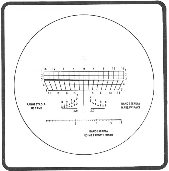
With the tube immobilized, the operator should fix the bore sight onto an object at 900+ meters. The object should have some distinct horizontal and vertical features. Once this is sighted, the mechanical sights can be checked. Russian style sights do not have much adjustment to them, but the Chinese family has full windage and elevation adjustment available. Bring the sights in line with the bore sight and the sights are aligned with the tube at all ranges. The scope itself has a single crosshair up above the sighting chart, distinct and by itself. This crosshair is to match the bore sight at 900 meters. Right and left windage and up or down adjustment are controlled by two dial knobs at the front of the sight. Full adjustment will be described in a later article.

Early style RPG-7 optical sight pouch contains spare bulbs, spare batteries, and various lens covers for low light, bright light, and haze, as well as the low temperature battery wire set. Modern sight carriers are molded plastic.
Low temperature battery wire set allows the operator to remove the battery from the optical sight and use it remotely. The battery fits inside the operator’s shirt pocket to keep body heat on the battery. The wire connects the battery to the optical sight. It is somewhat awkward but an excellent solution to low light/ low temperature situations. Don’t forget that the sight has an adjustment for low temperature aiming as well.

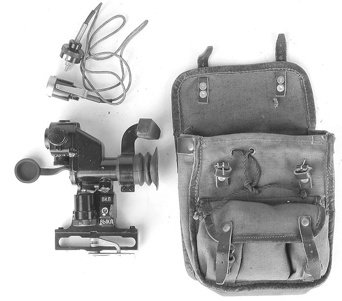
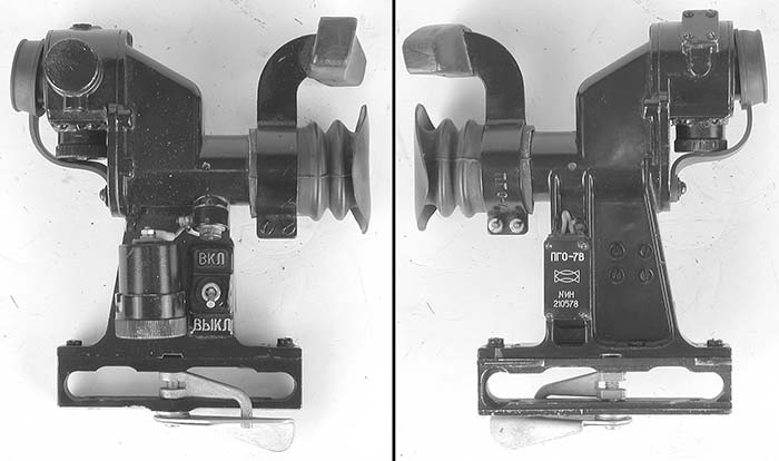
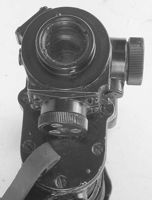
The Controversial Optical Sight

Optical sights are controversial because there are several schools of thought on this unit, and it does in fact take a lot of training and live fire practice to use the RPG-7 let alone the optical sight. SAR will be covering the sighting in depth at a later date. Suffice it to say that using this unit requires extensive training.

Russian/Soviet-style sight reticle. Note that the tank height is defined at 2.7 meters. This is an average of NATO and Warsaw Pact height tanks, and the operator should be aware at all times what the enemy tank heights really are and adjust accordingly.
Chinese family optical sights have two tank height stadia. The left stadia labeled 3.0 meters is for US tanks, and it has a second, lower line for gauging the distance of human targets with the Chinese bounding frag round. It is also used for smaller vehicles. The right stadia labeled 2.3 meters is for Warsaw Pact style tanks. The Chinese also added a straight line stadia at the bottom for gauging distance using the length of a tank.
This illustration shows the effect of crosswind on the flight of an RPG-7 grenade. It is the opposite of what one might think, and the opposite of the M72 LAW rocket. While the RPG-7 rocket is firing, the grenade turns into the wind, it does not drift with it. This is due to the location of the turbine and the fin stabilizers. Once the rocket motor has burned out, drift sets in and the grenade will travel with the wind. Distance obviously matters a lot in the planned point of aim, and the operator has to take into account where the rocket will burn out.
Percentage of hit comparison with 0 wind and 7 mph wind. This illustrates why in crosswind situations at longer distances, the operator will be concentrating on where the first round hits, because he will likely need to refine his aiming for a back up shot.

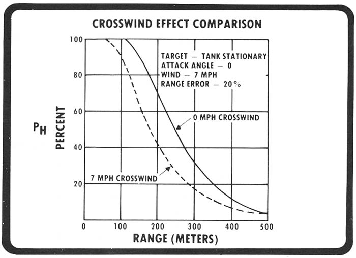
Advice is frequently given that an operator should immediately throw away the optical sight because it is too complicated for combat conditions. This is good advice if the operator is not going to receive a lot of the proper training; novices should stick to the iron sights. However, most RPG-7 operators are dedicated to this job and do receive a lot of training. If that is the case, the optical sight gives many advantages. Combined with a modern laser range finder, the optical sight can truly extend the range of the RPG-7 from its “point-blank” designated 300 meters to a full 500 meters, depending on wind conditions.

Again, experience with live fire is critical to the RPG-7 operator’s accuracy. In the US, it is difficult to get this experience due to our importation laws on explosives and the fact that the US military has a very wise policy of not allowing the firing of captured ammunition of this type. (In the event that there are US end users reading this who need to arrange live fire training outside the US, please see me after class. – Dan)
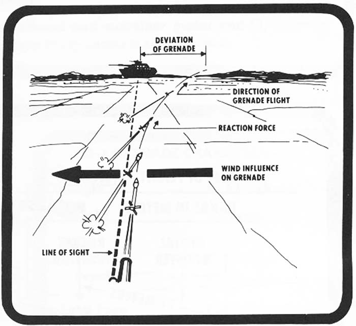
Understanding the basic RPG-7 Anti-Tank Round

The Wind Thing

RPG-7 Rounds

There are many, many rounds on the market today. SAR will cover these at another time. For our purposes, we are going to take a look at the basic HEAT (High Explosive Anti-Tank) round: the PG7B.

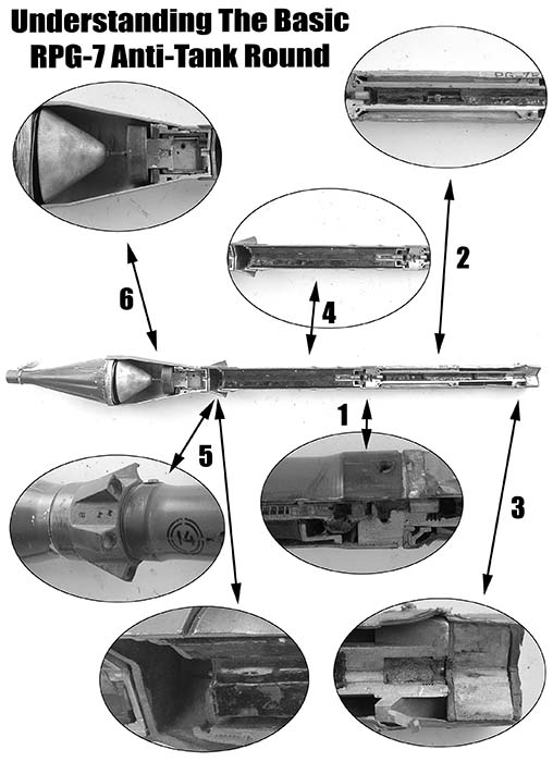
1) At the joint between the expeller charge and the rocket booster that is permanently part of the grenade, is the section that initiates the firing sequence. When the firing pin strikes the primer (located in the small threaded hole on the center side in this photo, but primer is missing) the primer ignites a train of events. Immediately the expeller charge to the left in this photo is ignited. The pyrotechnic pellet in the rocket booster is ignited when enough forward momentum has compressed the spring to the right in this photo, driving a second primer onto a fixed firing pin. This is a timed and blocked event- the rocket motor ignition delay is separated from the primer flash channel by solid aluminum. The pellet burns in a set time to ignite the rocket booster when it reaches 11 meters in front of the launcher.

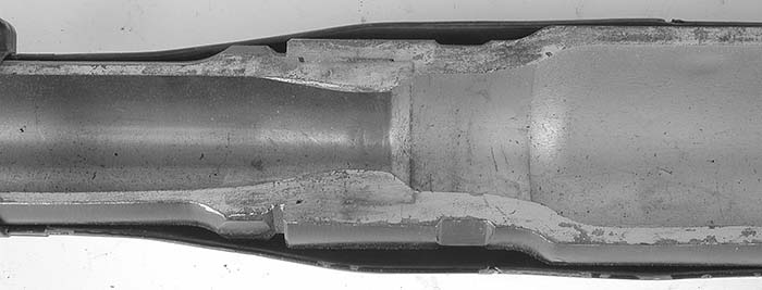
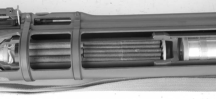
2) When the primer ignites, the expeller charge is fired off by the black powder in the center of the expeller tube. The expeller main charge propellant is double base NC/NG placed evenly around the central tube, in between the folded stabilizer fins. This is all wrapped with impregnated cardboard and a glued, waterproof tissue. This section is extremely vulnerable to moisture, so it is important to only remove from the carrying case just prior to firing. The expeller in an RPG-7 is now in an expansion chamber that is larger than the 40mm tube, so the expanding propellant gases rapidly build pressure and exert it onto the grenade.

3) At the rear of the expeller charge is a hard foam plug. As pressure builds in the expeller chamber, the grenade has forward pressure on it and eventually this plug breaks up and the parts of the plug and any unburnt cardboard are expelled out through the venturi and the blast cone. Directly in front of the plug is an aluminum turbine that imparts rotation immediately as the grenade shaft leaves the expeller chamber and tube.

4) As the grenade leaves the RPG tube, it has been “boosted” out by the expeller charge. Forward motion allows the four stabilizer fins to extend out to the sides, and it is important to remember this when firing as there must be at least 8 inches of clearance above all obstacles in the flight trajectory. This is also a good time to point out another reason not to install the expeller cartridge onto the rocket and carry it around. If this is bent or damaged then the entire trajectory may be thrown off. The pyrotechnic pellet will burn through to ignite the rocket booster, as long as the spring held block is out of the way due to proper forward momentum. Propellant gases begin the booster action at 11 meters from leaving the tube of the launcher.

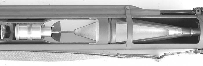
5) The rocket motor burns and the gases push forward into the nozzle block expansion chamber at the front joint just behind the grenade body. This chamber has six holes that point to the rear and outward, and the pressure from the gases blows out the seals and the six holes drive the grenade assembly forward during its assisted flight. It is important to note that the holes are canted in a direction opposite that of the rotation imparted by the fins. The spin rate imparted by the four fins is slowed after rocket ignition. This prevents overspin, and reduces spin degradation of the shaped charge on firing. Just behind the nozzle block is an elastic ring that holds the RPG-7 round in the launcher so slight downward firing is possible without the round coming forward and misaligning the primer and firing pin. When the rocket burns out, forward momentum keeps the grenade airborne until it reaches a target or approximately 900 meters where the safety fuze causes the nose cone area to explode. This does activate the shaped charge, although this author has observed many RPG-7 rounds that reached the five second mark, the safety detonated, and the shaped charge was still intact.

6) Cutaway view of the shaped charge. The piezo-electric nose fuze fires a spark plug system at the rear of the shaped explosive content. As the detonation wave moves through the explosive, the tin coated copper cone at the center is transformed to a high-speed, high-temperature jet of metal that penetrates up to 13 inches of steel armor.

Arming

Above Left: Standard PG-7 nose fuze cover in place. Cover should not be removed until directly before firing, and whether the fuze cover and safety is removed before loading or after loading is local command doctrine. For a single operator it is easier to remove the cap and safety pin before loading. The fuze is rated to be safe for a three meter fall. Above Center: Remove the safety pin using the pull tape. Retain pin and cap in pocket in case of having to remove and store the grenade. Re-install in the same manner. Many operators keep a couple of sets of cover and safety pin in a front pocket, and simply discard the covers as they are used so they don’t have to be concerned under combat conditions about whether they have a cap and safety should they need it. Above Right: PG-7 grenade nose fuze ready for firing. The fuze contains direct pressure piezo electric firing as well as timed fuze self destruct capabilities. Some modern designs have a grazing hit feature.

Firing sequence

Firing the RPG-7 series of weapons is considered a two man operation: the operator and assistant gunner. Both should be proficient with the system and should have a lot of live fire training. The skills needed to hit a target with an RPG can not be gained from simple training drills, especially firing at longer ranges. When the RPG team is “hunting,” it is just as important to figure in attempting to conceal their position and the backblast signature from the enemy as it is to find good front cover. In the case of needing a second shot, the backblast will frequently have located them for the enemy. Aiming so that the rear of the RPG-7 is pointed around the corner of a large building or hill can help with this. A couple of safety points should be emphasized. Behind the tube, for about 30 meters, there is a 70 degree danger zone. Close to the tube is a kill zone. The operator and his A-gunner should always be ensuring that there are no obstacles, walls, etc within 2 meters behind the RPG. Good advice would be to make that at least 3 meters. Blastback can be quite deadly. Firing from inside a small room is to be discouraged. We at SAR have been told that there exists a video clip of an Iraqi insurgent firing an RPG-7 from a third floor window with the backblast hurling him forward out the window. If you have this clip, please forward it to us. It contains sage wisdom for all potential operators.

This graph gives a good rule of thumb for the operator. Modern RPG=7 rounds all have self-destruct fuzes, and the fuze is set to go off at approximately 900 meters, or five seconds of flight time.

The operator and A-gunner will have worked together and developed their own method of communicating these sequences, but it is advisable for the A-gunner to be on the left of the operator and reach across to load. This may not always be practical, but it is part of many countries’ training doctrine. Using today’s quality range finders is very important, as accurate range distance should increase first round hit probability. Once the pair have stalked their target, found range and target speed, and set up the firing position, the following sequence of events should occur:

  • A-gunner visually clears the tube, then prepares the rounds to be fired, attaching the expeller charges.
  • Operator ensures the push through safety is to the right and the hammer is not cocked, then announces “Load”.
  • A-gunner loads a round into the tube, ensuring the index is properly occurring and the elastic gasket is snugly in place holding the round in the tube, then visually examines the backblast area for friendlies, to ensure there is no danger to the rear, and to ensure that various and assorted Operator and A-gunner appendages are out of the blast area. He announces “Clear to fire”.
  • Operator announces “Ready” and the A-gunner removes the fuze protector and arms the grenade (this may have been done before loading). A-gunner resumes watching backblast area for friendlies and gives warning to the operator if the situation changes.
  • Operator cocks the hammer, takes careful aim, pushes the safety to the left, then, squeezing the trigger, he fires. The operator then analyzes shot effect and decides whether to reload and repeat, or to depart the area with all due haste.
  • In the event of a misfire, the operator announces “Misfire,” then pushes the safety to the right and “On,” announces “Safe” and the A-gunner makes a fast visual inspection to see if the grenade was properly indexed or not. High probability in a misfire will be that the grenade was not properly seated. If that is the case, the A- gunner then immediately reseats the grenade and initiates checks. Operator fires again. If the grenade was in place, then the A-gunner should pull the grenade forward and visually inspect the primer for a hit. If no hit, try again. If there is a dented primer, then the grenade should be gingerly moved away from the area and left for EOD (on the range) or blown in place at the first opportunity if in the field.
  • If there is another misfire, then the A-gunner removes the grenade and inspects the primer. If there is no hit on the primer, then there must be a full check done on the pistol group and firing pin. The A-gunner should re-install the fuze cover and safety pin, then remove the round and unscrew and store the expeller charges and grenades in their carry cases. Under no circumstances should the expeller charges be left attached to the grenades and carried around. The reasons for this should be clear from the discussion of how the rounds work.

Defending against the RPG

View of cutaway RPG-7 HEAT round. On the right, the outer ribbed cone is the standoff, and it creates the outer path of the ignition circuit that continues the entire length of the warhead. Just underneath it, observe the inner cone that creates the inner electrical path. The space between them is an open air insulator area. This is the section that chain link fence defenses are intended to fracture, short circuit and disrupt.

A couple of quick notes on defending yourself against RPG-7 attacks. Unfortunately, for most vehicles it is not practical to put up any fencing around the vehicle. Perhaps the best defense is high speed and evasive maneuvering. Don’t drive one constant speed or straight path. The other helpful hint goes to suppressive fire – keep their heads down. If you are hit, remember that a back up shot will probably be coming soon – within 8-12 seconds.

When an RPG-7 is fired towards your position, there are three basic signatures. The first and second are simultaneous: the flash and 30 meter blast area behind the operator’s position, and the flash to the front of the operator (minimal). The third is that approximately 11 meters in front of the operator, there will be a larger puff of smoke where the rocket motor kicks in. This is generally quite visible and a good basis for aiming return fire. If you are in the line of fire, just aim back into the area and suppress. If you are oblique to the line of fire (e.g. the RPG was firing at a vehicle in front of you) aim back 11 meters from the puff and put the hammer down on your guns.

In this cutaway view, we can see that the firing pin at rest does not enter the tube, and when it does, the proper firing pin protrusion that it is capable of. This does not mean this is the proper firing pin protrusion when firing, just that it has not been interfered with. Since the hammer is under its own momentum when it strikes the firing pin and not under hammer spring pressure, the firing pin receives just enough pressure to solidly strike the primer. This obviously can not be seen in a complete launcher, but a quick view from the front looking down the empty tube towards a light surface will show whether the pin is operating properly. Press the firing pin in from the hammer view to ensure there is spring resistance. If no resistance, replace the spring.

During the Vietnam War, US forces began building portable fencing structures on their vehicles. This was chain link fence or very tight barbed wire. The goal was two fold. First, the fence could catch the round in mid-flight, holding it and keeping it away from the vehicle. If the round then detonates it will not penetrate the armor. Most RPG-7 rounds are designed as shaped charges, so they need to be approximately two inches from the surface of the target when they go off, or they are ineffective. Rounds that have a self-destruct fuze will explode 5 seconds after firing, even if trapped in defensive fencing. This is a danger to soldiers who are unprotected. While the AT rounds are not designed as anti-personnel, there can be enough fragmentation and blast to kill or cause other casualties to those near the explosion. The second reason for the fencing is due to the manner in which the traditional RPG-7 rounds operate. There is a double cone in the front of the stand-off area. The space between the two cones is intended as the path for the peizo electric fuze to ignite the main fuze on the shaped charge. It is quite effective, but if the round strikes the fencing and this cone area is distended and broken, the fuze can’t operate. Newer rounds have a bypass system in place so the best the defender can hope for is to hold the round in fencing, away from the skin of the vehicle, when it explodes. Damage to unprotected personnel can be expected. In the event that the nose fuze strikes a strand of the fence, the round will detonate away from the vehicle, nullifying the shaped charge effect.

The firing pin plug is squared into its well when properly threaded into place. This is on an RPG-7D.

Armorer’s Hints for the RPG-7 Series and the RPG-2

Disassembly of the RPG series at the operator level is confined to removal of the trigger group, the heat shields, scope, and performing inspection and maintenance on these items. There are a number of cleaning tools supplied including a large brush and swab. The interior of the tube is chromium lined but needs frequent cleaning during use due to the corrosive nature of the powder in the expeller charge, as well as how the expeller charge operates. The charge has paper, foam, and burning propellant that is supposedly expelled through the venturi and to the rear, but on occasion particles remain that can either block the next round from being properly inserted, or lead to corrosion. Once the tube is cleaned, a very, very, light coat of oil should be applied internally.
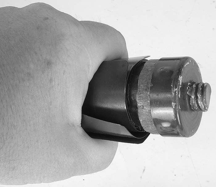
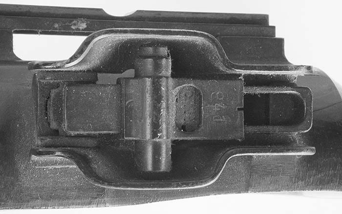
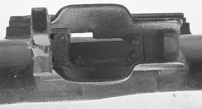
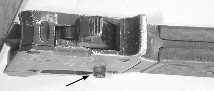
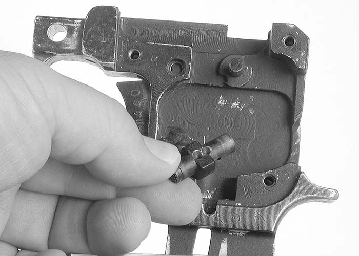
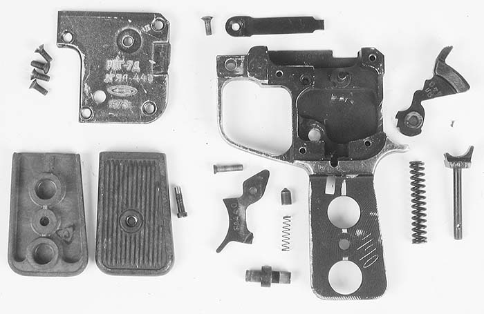
Firing Pin

Firing pin plug has been threaded out using a common wrench. Damage can be seen on the plug from previous operators using improper tools that slipped off. The plug should be replaced in this condition. A very light coating of anti-seize compound should be applied to these threads.
Left to Right: Firing pin plug, firing pin with spring, firing pin cup. All parts should be inspected for wear, chipping, or breakage.

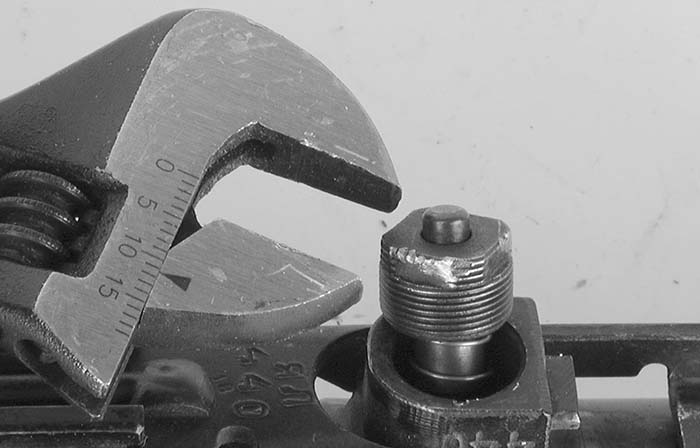
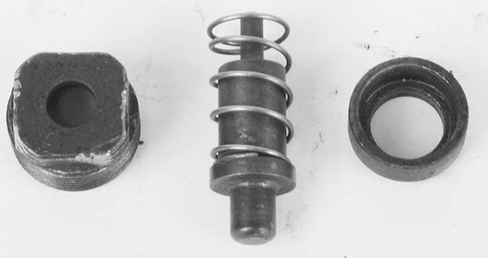
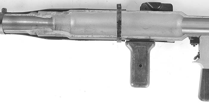
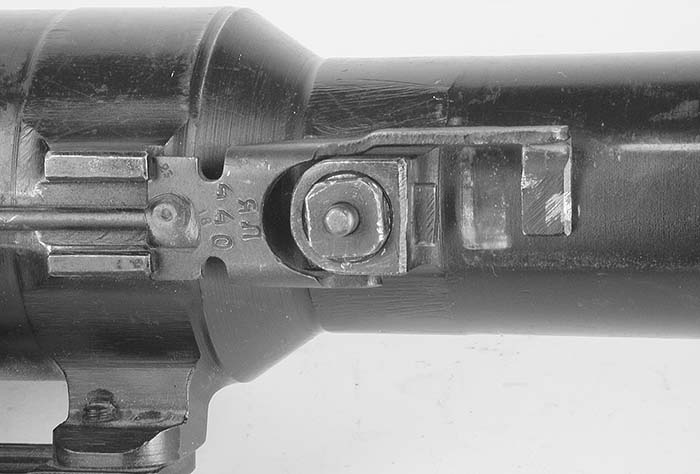
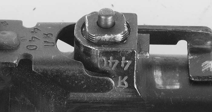
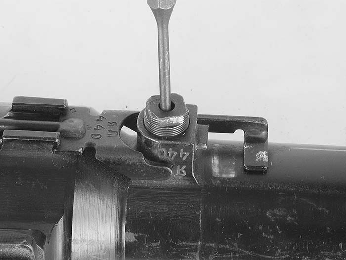
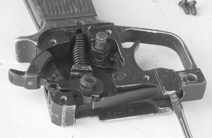
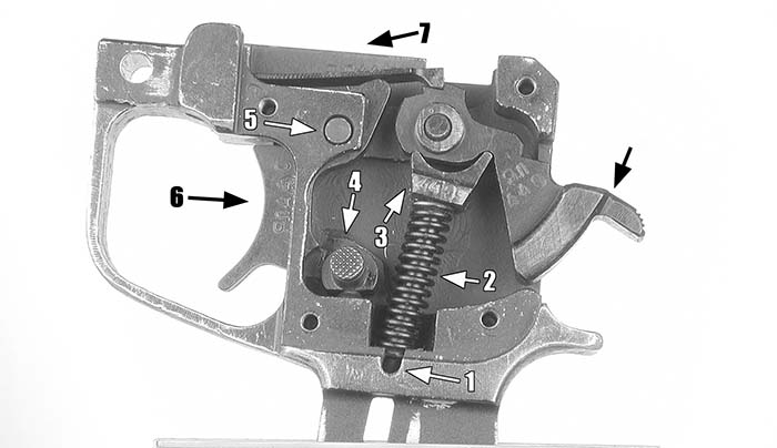
The firing pin location and projection are key to the operation of these systems – and are very basic. There is a double headed pin with a barrel body, which is held in a well in the bottom side of the launcher. One pin is smaller and is the firing pin. The other larger diameter pin is for the hammer to strike. The firing pin hole in the body is aligned with where the primer on the grenade body should be. Any misalignment or change in the extension of the firing pin into the primer will affect the reliability of the firing sequence. The firing pin is held in position by two pieces: a cup that is replaceable and locates the pin in the well, and a threaded plug that holds it into the well. The plug has a hole in it that mirrors the firing pin hole, allowing the striking end of the firing pin to face the hammer. The central body of the firing pin has a spring coiled around it, which keeps the firing pin from entering the firing pin hole unless the hammer has struck it.

Tip for reassembly: Once you have the cup, the firing pin and spring, and the plug in place, and have started threading the plug in, use a pin punch to ensure the firing pin can travel all the way in. Then, holding the punch in place, thread the plug in around it. Snug the plug square and just beyond hand tight.

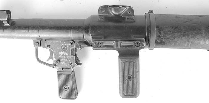
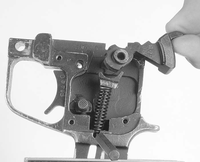
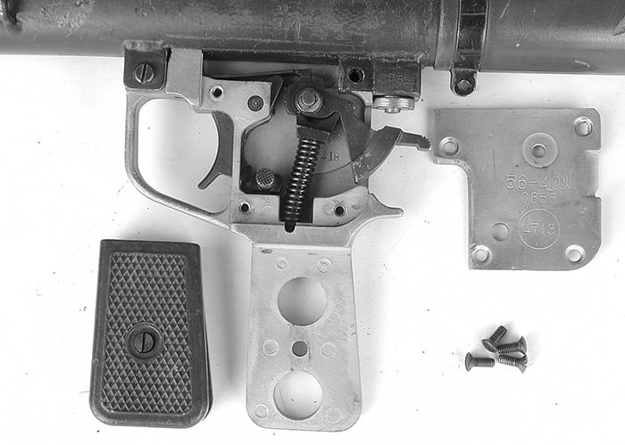
Disassembly of Trigger Group

Trigger group from RPG-7V circa 1966 being removed by pushing the split take down pin out, then rocking the assembly downward.
View from the rear of RPG-7 trigger group showing the push through safety extended on the left side. This is the “Fire” position.

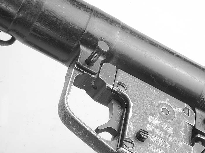
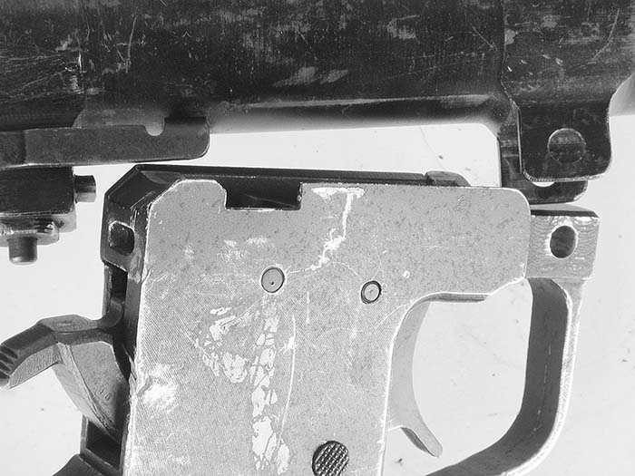
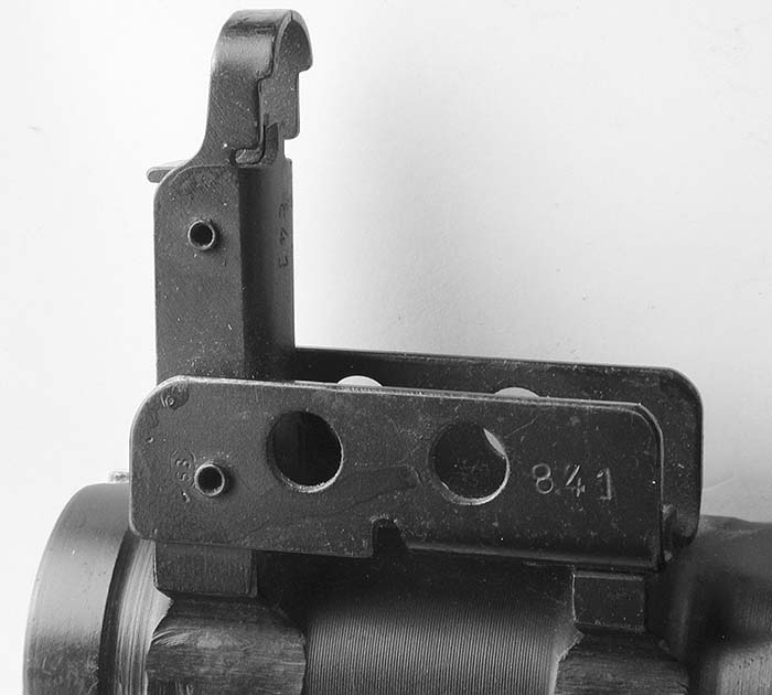
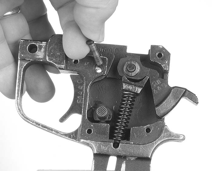
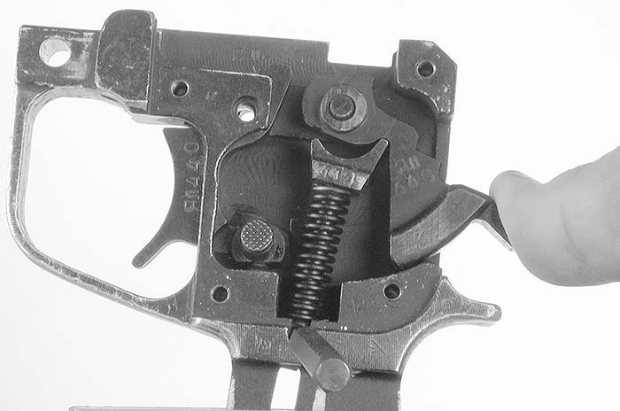
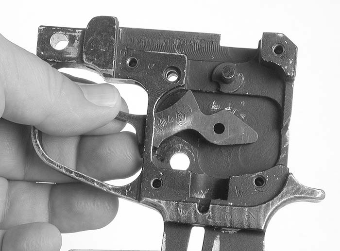
Most shooters will recognize the internal parts design from numerous single shot hammer fired rifles and shotguns. The design is not unusual. The group is held in position by a fixed lug at the rear and a push through split takedown pin at the front. In the case of the B-40, the front is frequently held in by a screw. There are other variations and removal should be obvious by what method is used. There is a push-through trigger blocking safety, and the hammer is manually cocked. Once cocked, the safety is engaged; left to right from the operator’s view is “Safe” and pushing through from right to left is “Fire.” This can be accomplished using the inside of the index finger, which rests in that area when holding the grip. When the hammer is cocked, the sear engages it and holds it under spring tension from the hammer spring. Once the safety is off, and the trigger pulled, the hammer moves rapidly upward under tension, but it is the momentum of the hammer itself that causes it strike the firing pin. The hammer spring is mechanically kept from forcing the hammer all the way to the top of its cycle. There would be too much force in that case, thus the mechanical block. The cycle repeats.

With the hammer in the fired position, remove the four flat head screws in the side panel and remove the side panel.
Remove the sear (flat spring) from the top of the group using a flat head screwdriver. Remove the grips from the group by unscrewing the single screw at the center of the grips.

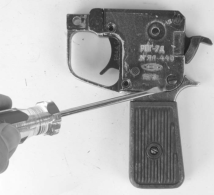
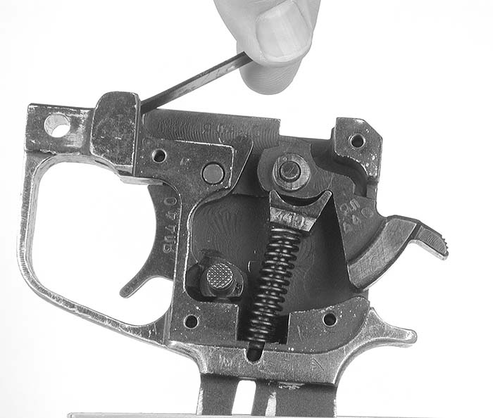
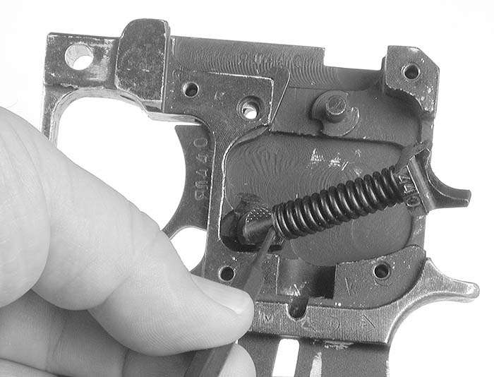
Disassembly is in the following manner, with one exception. The early RPG-2 and B-40 type trigger groups may have the pin hole for the hammer spring removal in such a manner that the pivot and spring must be removed under pressure. Early armorers had a program to drill out a straight well so that once contained under pressure, the spring could be removed in that contained state and replaced on reassembly.

Trigger group with grips removed has been placed in a soft jaw vise for ease of disassembly. It is entirely possible to do this by hand, but the safety in particular requires three hands or a very experienced touch. 1: Hammer spring / Pivot removal well, 2: Hammer Spring, 3: Hammer Pivot, 4: Push through safety, 5: trigger retaining pin, 6: Trigger, 7: Sear, 8: Hammer.
Removal of the sear, if not done before putting in the vise.
Remove the trigger pin. It is a one headed pin that can only be inserted in one direction.
Depress the hammer about half way until the hole in the hammer pivot rod is below the base of the spring, in the removal well. Insert a pin punch or improvised tool into the hole, locking the spring in a compressed condition. This takes spring pressure off of the hammer.
Lift the hammer off of its pivot and remove it.
Remove the hammer spring on the hammer pivot rod. Leave this held under tension for re-installation. If it is necessary to remove the spring, then use a vise and it is possible to re-install this by pressing against the edge of a table, but if possible, make a tool from small pipe with a channel in the side, then compress in a vise and insert a pin to hold the spring under tension. There is a standard tool for this in the operator’s kit, but it is frequently lost or tossed to save weight. Bad move. The tool is quite handy.
Remove the safety and the detent and spring under it. On re-assembly, the spring and detent go into place, insert a flat head screw driver from the back of the group and hold the detent under pressure, while sliding the safety into place – pushing the screwdriver out of the way in the process. The safety is held in on one side by the rear wall of the trigger group, and by the removable plate on the other side.
Slide the trigger out of the trigger well. Reassembly is the reverse of these steps – always put the trigger in first, then the safety and detent.
RPG-7V trigger group disassembled.
Soviet RPG-2 trigger group. Note that the pin hole has been elongated to allow for the removal of the hammer spring under tension.
Chinese RPG-2 trigger group. Note that the pin hole has been elongated to allow for the removal of the hammer spring under tension.

Send questions to: Raffica sareview@aol.com
Or mail to Small Arms Review Attn Raffica
631 N. Stephanie St #562
Henderson, NV 89014

This article first appeared in Small Arms Review V10N3 (December 2006)

Author

  • SAR Staff
    SAR Staff

    View all posts

Tags: 2006Dan SheaGerman PanzerfaustHEATHigh Explosive Anti-TankM57PanzerfaustRPG-2RPG-7RPG-7 RoundsRPG-7 SystemRPG-7DRPG-7VSheaType 56Un-Exploded OrdnanceUXOVolume10N3
Previous Post

INDUSTRY NEWS: IMPORTERS ADDRESS U.N. GUN CONFERENCE

Next Post

INTERVIEW WITH DOLF GOLDSMITH

Next Post

INTERVIEW WITH DOLF GOLDSMITH

TRENDING STORIES

  • U.S. NAVY MK18 MOD O CUSTOM CLOSE QUARTER COMBAT WEAPON FOR THE SEAFARING SERVICE

    U.S. NAVY MK18 MOD O CUSTOM CLOSE QUARTER COMBAT WEAPON FOR THE SEAFARING SERVICE

    0 shares
    Share 0 Tweet 0
  • Recreational Use Of 40MM Grenade Launchers

    0 shares
    Share 0 Tweet 0
  • Customizing the Already Custom SIG P320 Spectre Comp

    0 shares
    Share 0 Tweet 0
  • Col. Rex Applegate: The Knife Designs of a Close-Combat Legend

    0 shares
    Share 0 Tweet 0
  • Evolution of the U.S. Grenade Launcher From World War II to Today’s Conflicts

    0 shares
    Share 0 Tweet 0
  • Trending
  • Comments
  • Latest
U.S. NAVY MK18 MOD O CUSTOM CLOSE QUARTER COMBAT WEAPON FOR THE SEAFARING SERVICE

U.S. NAVY MK18 MOD O CUSTOM CLOSE QUARTER COMBAT WEAPON FOR THE SEAFARING SERVICE

Recreational Use Of 40MM Grenade Launchers

Recreational Use Of 40MM Grenade Launchers

SIG Spectre Comp with AXG Grip Module

Customizing the Already Custom SIG P320 Spectre Comp

Col. Rex Applegate: The Knife Designs of a Close-Combat Legend

Col. Rex Applegate: The Knife Designs of a Close-Combat Legend

New Review: V19N1

New Review: V23N3

SAR|Special

SAR|Special

The Grand Power Q100

The Grand Power Q100

A Fading Star: The star S135 Submachine Gun, That is

A Fading Star: The star S135 Submachine Gun, That is

The Iron Door: Soviet Russian Weapons Designers Stop the Germans in Their Tracks

The Iron Door: Soviet Russian Weapons Designers Stop the Germans in Their Tracks

The American FN FAL Rifle: In Search of the Perfect Lightweight Rifle

The American FN FAL Rifle: In Search of the Perfect Lightweight Rifle

Ahead of Its Time: British Fosbery Pump-Action Shotgun with “Stoner” Bolt

Ahead of Its Time: British Fosbery Pump-Action Shotgun with “Stoner” Bolt

The Big Bang! : Great American Fun at the 2018 Big Sandy Machine Gun Shoot in Wikieup, AZ

The Big Bang! : Great American Fun at the 2018 Big Sandy Machine Gun Shoot in Wikieup, AZ

QUICK LINKS

  • About Chipotle Publishing
  • About Small Arms Review
  • Advertise with Us
  • Write for Us

CONTACT DETAILS

  • Phone: +1 (702) 565-0746
  • E-mail: office@smallarmsreview.com
  • Web: www.chipotlepublishing.com
  • Chipotle Publishing, LLC 631 N. Stephanie St., No. 282, Henderson, NV 89014
Small Arms Review

FOLLOW US

  • Privacy Policy
  • Disclaimer

© 2022 Chipotle Publishing | All Rights Reserved

No Result
View All Result
  • Home
  • Articles
    • Guns & Parts
    • Suppressors
    • Optics & Thermals
    • Ammunition
    • Gear
    • News & Opinion
    • Columns
    • Museums & Factory Tours
    • ID Guides
    • Interviews
    • Event Coverage
    • Articles by Issue
      • Volume 1
      • Volume 2
      • Volume 3
      • Volume 4
      • Volume 5
      • Volume 6
      • Volume 7
      • Volume 8
      • Volume 9
      • Volume 10
      • Volume 11
      • Volume 12
      • Volume 13
      • Volume 14
      • Volume 15
      • Volume 16
      • Volume 17
      • Volume 18
      • Volume 19
      • Volume 20
      • Volume 21
      • Volume 22
      • Volume 23
      • Volume 24
  • The Archive
    • Search The Archive
  • Store
    • Books
    • Back Issues
    • Merchandise
  • Podcast
  • Newsletter
  • Events
  • FrankenGun Challenge
  • About
    • About Small Arms Review
    • About Chipotle Publishing
    • Contact Us
    • Other Publications
      • Small Arms Defense Journal

© 2022 Chipotle Publishing | All Rights Reserved

Welcome Back!

Login to your account below

Forgotten Password?

Retrieve your password

Please enter your username or email address to reset your password.

Log In

Add New Playlist

This website uses cookies. By continuing to use this website you are giving consent to cookies being used. Visit our Privacy and Cookie Policy.

Subscribe To Our Weekly Newsletter

Are you in the know?
Stay up to date with the latest articles.

Facebook-f Linkedin Instagram

Redirecting to External Website

You are leaving the Small Arms Review website and will be redirected to an external link in a 5 Seconds.
VISIT NOW!